Dicycle surface plasmon super-slow wave planar microwave delay line

A surface plasmon and microwave delay technology, which is applied in the direction of delay lines, electrical components, waveguide devices, etc., can solve the problems of high signal propagation speed, low operating frequency, and difficult integration, and achieve low propagation speed and time Uniform, size-reducing effect

Active Publication Date: 2018-07-27
NANJING UNIV OF POSTS & TELECOMM
View PDF4 Cites 6 Cited by
  • Summary
  • Abstract
  • Description
  • Claims
  • Application Information

AI Technical Summary

Problems solved by technology

The inductance-capacitance delay line with lumped parameters has a low operating frequency
The transducer structure of the ultrasonic delay line is complicated, it is not easy to integrate with the system components, and the working frequency is not high
Optical fiber delay lines have the advantages of wide bandwidth, low loss, anti-interference, and good confidentiality, but the structure of optical fiber delay lines is quite complicated and difficult to integrate, and the cost is high
Commonly used delay lines for microwave transmission lines include microstrip delay lines, coplanar waveguide delay lines, and stripline delay lines. However, in these delay lines, the main mode of electromagnetic waves is TEM mode or quasi-TEM mode, and the propagation speed of the signal is still higher, so that the size of the delay line is still relatively large
Moreover, because it is a dual-conductor transmission line, the lateral dimension of the transmission line is large, and the mutual coupling between adjacent transmission lines is strong

Method used


Image

  • Dicycle surface plasmon super-slow wave planar microwave delay line
  • Dicycle surface plasmon super-slow wave planar microwave delay line

Examples


Embodiment Construction

[0019] The present invention will be further described below in conjunction with drawings and embodiments.

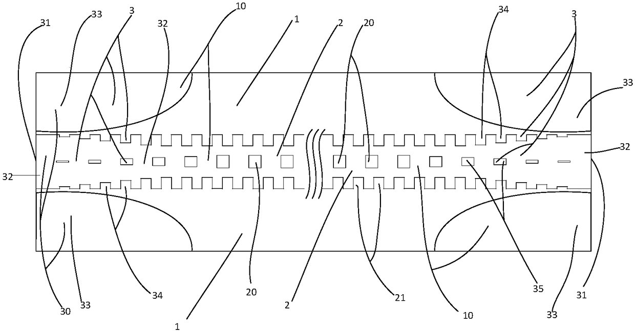
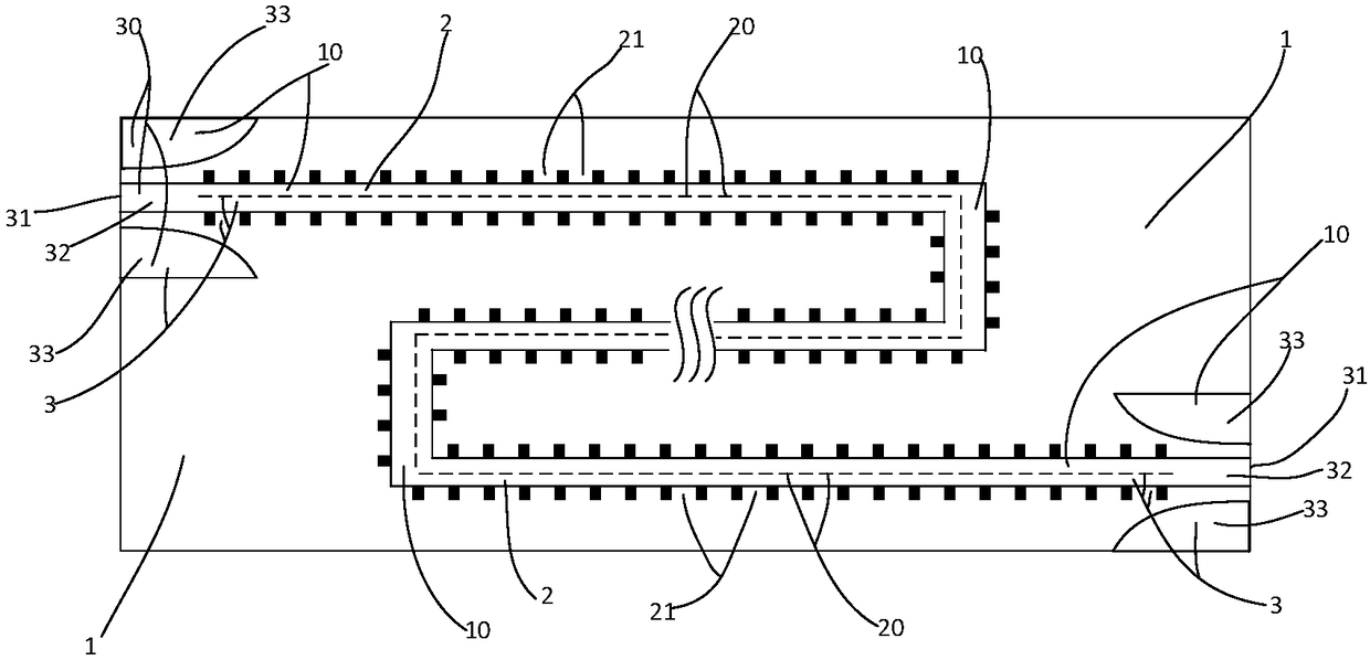
[0020] The embodiment adopted in the present invention is: a dual-period surface plasmon ultraslow wave planar microwave delay line includes a dielectric substrate 1, a surface plasmon transmission line 2 arranged on the dielectric substrate 1, and a coplanar waveguide to Surface plasmon transmission line transition 3; metal layer 10 on one side of dielectric substrate 1, metal layer 10 constitutes surface plasmon transmission line 2 and coplanar waveguide to surface plasmon transmission line transition 3; surface plasmon transmission line 2 The two ends of the two coplanar waveguides are respectively connected to the surface plasmon transmission line transition 3, and the surface plasmon transmission line 2 is a transmission line with a double-period periodic structure, along the center line of the surface plasmon transmission line 2 A rectangular inner slot 20 array i...


PUM


Abstract

The invention discloses a dicycle surface plasmon super-slow wave planar microwave delay line comprising a dielectric substrate (1), a surface plasmon transmission line (2) arranged on the dielectricsubstrate (1) and coplanar waveguide to surface plasmon transmission line transition apparatuses (3), wherein two ends of the surface plasmon transmission line (2) are separately connected with two coplanar waveguide to surface plasmon transmission line transition apparatuses (3), the surface plasmon transmission line (2) is the transmission line of a dicycle structure, and a rectangular inner groove (20) array and a rectangular groove (21) array are arranged on the surface plasmon transmission line (2); and the working frequency band of the delay line is close to the high cut-off frequency ofthe surface plasmon transmission line (2). The delay line is uniform in delay within the working frequency band, and small in mutual coupling and size; the delay line is of a planar structure, capable of bending, easy to integrate and low in production cost.

Description

technical field [0001] The invention relates to a microwave delay line, in particular to a double-period surface plasmon ultra-slow wave planar microwave delay line. Background technique [0002] A delay line is a common microwave passive component used in phased array and pulse compression systems. A delay line delays the time it takes for a signal to pass through itself. Due to the high speed of electromagnetic wave transmission, the size of the delay line is usually required to be small so as to provide the longest possible time delay in a small size. If the signal travels at the speed of light in air, a time delay of 1 microsecond requires a delay line of 300 meters. In order to reduce the size of the delay line, it is usually necessary to reduce the propagation speed of the signal on the delay line, and the delay line must be folded section by section. Commonly used delay lines for microwave signal delay include inductance-capacitance delay lines with concentrated pa...

Claims


Application Information

Patent Timeline
Patent Type & Authority Applications(China)
IPC IPC(8): H01P9/00H01P9/04
CPCH01P9/006H01P9/04
Inventor 杨梅李常中程崇虎刘蕾蕾
Owner NANJING UNIV OF POSTS & TELECOMM
Why Eureka
Try Eureka