Varistor with novel short-circuit protection device

A technology of short-circuit protection and varistor, applied in the direction of varistor, current response resistor, etc., can solve the problems of complex structure, poor shock resistance, slow heat conduction, etc., and achieve the effect of complex structure, poor shock resistance and high inductance

Inactive Publication Date: 2007-09-26
甘立刚
View PDF0 Cites 6 Cited by
  • Summary
  • Abstract
  • Description
  • Claims
  • Application Information

AI Technical Summary

Problems solved by technology

This technology refers to packaging the varistor and the thermal fuse in series, and using heat conduction to conduct the heat generated by the leakage current on the varistor to the thermal fuse. When the temperature rises to the set temperature of the thermal fuse, the thermal fuse Fusing, cutting off the varistor from the circuit, in addition to the life and reliability problems of the thermal fuse, there are also the following problems in using the thermal fuse to protect the varistor from overheating: the heat conduction path is long, the response speed is too slow, and in its structure The upper heat is first transmitted to the thermal fuse shell through a certain insulating material, then to the internal filling material of the thermal fuse, and finally to the melt of the thermal fuse. Therefore, the response speed of the thermal fuse is determined to be slow.
[0012] First, reduce some important characteristic parameters of varistors, such as flow capacity, life, power frequency withstand voltage, and high frequency characteristics in exchange for incomplete protection of varistors, which actually violates the use of varistors to a certain extent. The original meaning of the varistor
[0013]Second, these technologies adopt the open circuit protection mode when the varistor fails, and the basis for judging the failure is the temperature rise of the varistor
Due to structural reasons, it mu

Method used


Image

  • Varistor with novel short-circuit protection device
  • Varistor with novel short-circuit protection device
  • Varistor with novel short-circuit protection device

Examples


Embodiment Construction

[0074] The present invention will be described in further detail below in conjunction with the accompanying drawings and specific embodiments.
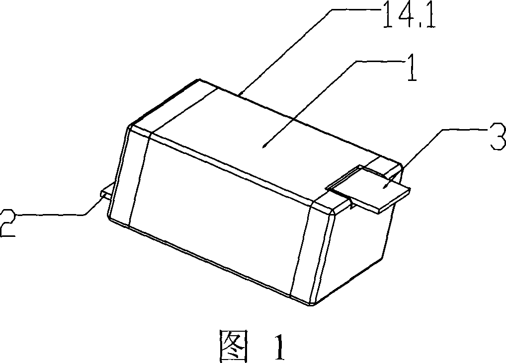
[0075] See Figure 1

[0076] Fig. 1 is a perspective view of a novel short-circuit protection device in the present invention. In Fig. 1, described a kind of piezoresistor 14 with novel short-circuit protection device 14.1 comprises insulator matrix 1, and electrode 2 and electrode 3 protrude from two ends in the body 1 of short-circuit protection device 14.1 respectively, and described electrode 3 has The function of heat transfer, conduction and fixed short-circuit protection device 14.1, the electrode 2 is used to connect with the lead-out pin 13 of the piezoresistor 14 (as shown in FIG. 4 ).
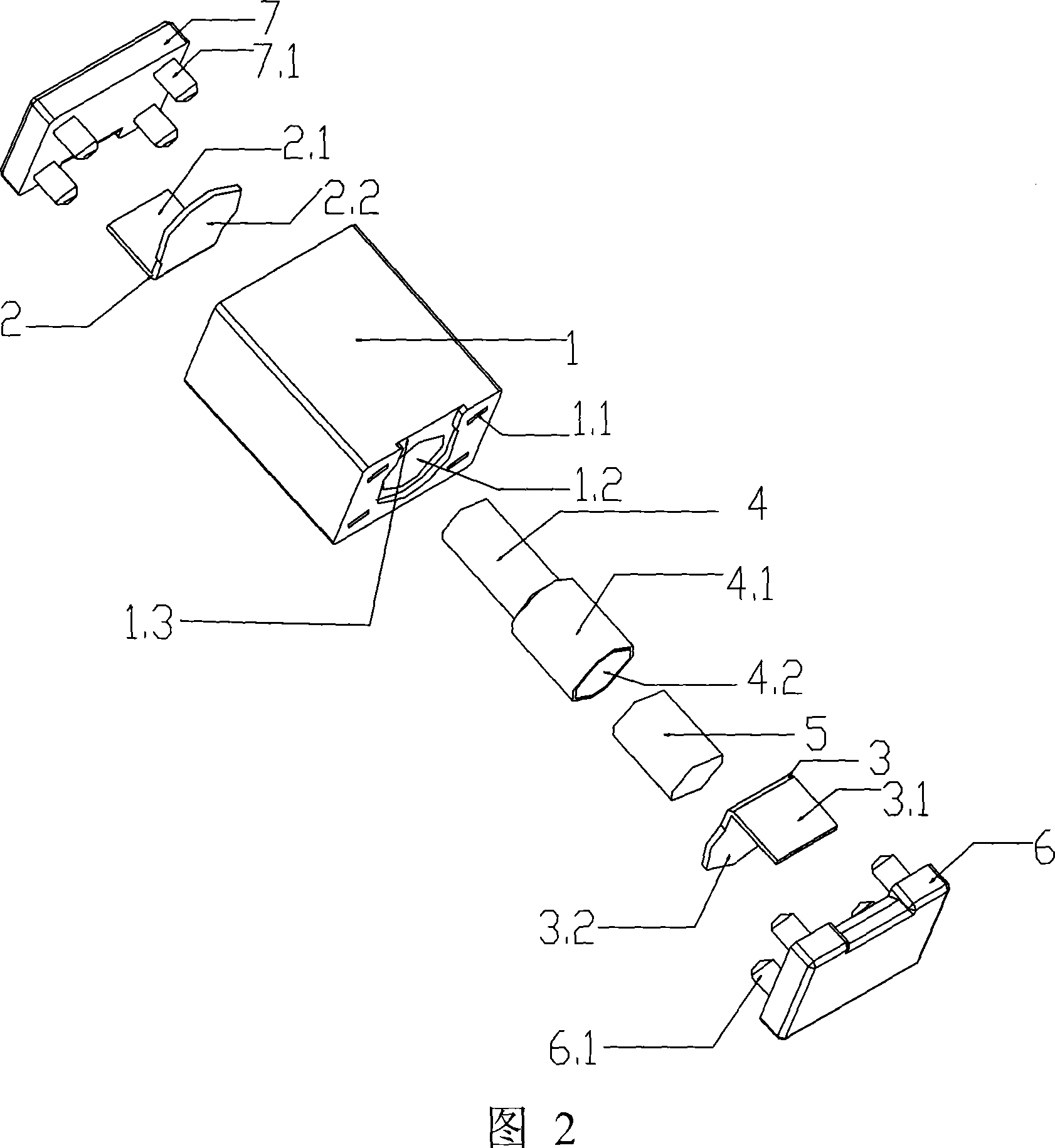
[0077] See Figure 2

[0078] Fig. 2 is an assembly drawing of parts of the novel short-circuit protection device of the present invention. In Fig. 2, the insulator matrix 1 and the insulator outer covers 6, 7 of the novel short protection...


PUM

PropertyMeasurementUnit
Melting temperatureaaaaaaaaaa
Lengthaaaaaaaaaa

Abstract

A type of piezoresistance equipped with new type short protecting device, the piezoresistance is parallel connected with the new type short protecting device, the short protecting device is hot melt body which at least includes two parts, thereinto at least one part is hollow part, the other part is solid part; the short protecting device includes insulator base noumenon, thermal deformation material subassembly, electrode, insulator outer cover; the insulator base includes through hole which is used to mount thermal deformation material subassembly and several mounting holes which is used to mount the insulator outer cover; the insulator base is equipped with fixed metal electrode; the thermal deformation material subassembly includes little conduit and big cannula which is set with thermal deformation material, temperature controlling weldable fusible alloy which is used to fill in the cavity of big cannula, the insulator outer cover includes protruding foot which matches with number and diameter of mounting hole and groove which spreads the insulator base noumenon. The invention is close mode protection, the structure is simple, and the safety is well, energy-saving, consummation is decreased, environmental protection, the operation is stable, and it is easy to detect; The efficiency is high, cost is low, and the service life is long.

Description

technical field [0001] The invention relates to an electrical component, in particular to a piezoresistor with a novel short-circuit protection device. Background technique [0002] With the rapid development of modern electronic and electrical technology, more and more electronic and electrical equipment (such as: electronic equipment, network equipment, household appliances, electricity, electrical, medical, computer integrated circuits, etc.) are widely used in various fields, and At the same time, these electronic and electrical equipment are all subjected to lightning surge natural disasters and various electromagnetic interference surge currents and surge voltages without exception, causing these devices to fail to work normally, and in severe cases, they will catch fire, burn, explode, etc. [0003] An effective way to solve the above problems is to connect one or more groups of MOV zinc oxide varistors in parallel at the input terminals of these devices to absorb var...

Claims


Application Information

Patent Timeline
IPC IPC(8): H01C7/10H01C7/13
Inventor 甘立刚
Owner 甘立刚
Why Eureka
Try Eureka