

High-performance time-digital converter circuit structure
A converter circuit, time-to-digital technology, applied in time-to-digital converters, analog-to-digital converters, instruments, etc., can solve the problems of unrealistic charging current, large charging current, slow capacitance, etc., to ensure correctness and processing speed. Fast and accurate timing effect
- Summary
- Abstract
- Description
- Claims
- Application Information
AI Technical Summary
Problems solved by technology
Method used
Image

Examples
Embodiment Construction
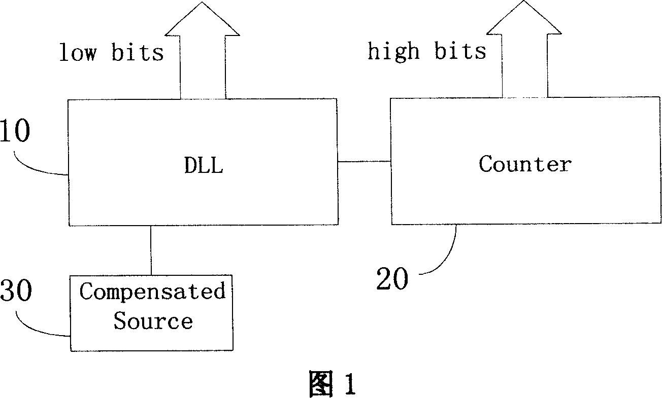
[0038] As shown in Fig. 1, a high-performance time-to-digital converter circuit architecture includes a delay chain loop (10) for generating low-order data, a counter (20) for generating high-order data, and a compensation control source (30).
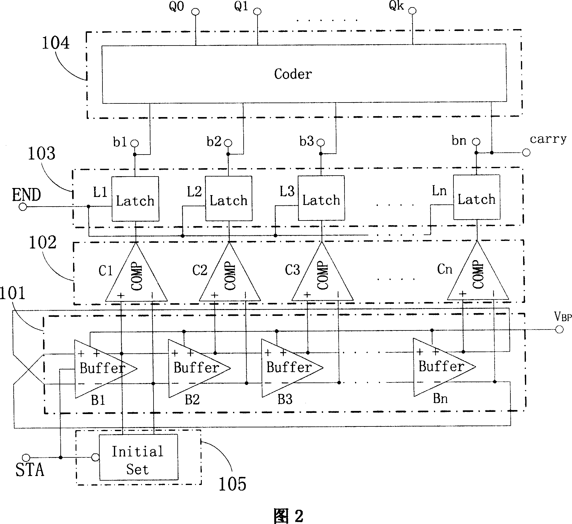
[0039] As shown in Figure 2, the delay chain loop (10) is composed of a delay unit loop (101), a group of comparators (102), a group of latches (103), an encoder (104) and an initialization unit ( 105) Composition.
[0040]The delay unit loop (10) is composed of n (n is a positive integer) buffers Buffer, each buffer Buffer has positive and negative two differential input terminals and positive and negative two differential output terminals, each stage of buffer Buffer and The non-inverting terminal of the next-level buffer Buffer is connected, the positive output terminal of the last-level buffer Buffer is connected to the negative input terminal of the first-level buffer Buffer, and the negative output terminal is connected to the po...
PUM
 Abstract
Description
Claims
Application Information