Static birefringent polarizing inteference imaging spectrometer

A polarization interferometer and interference imaging technology, applied in the field of remote sensing interference imaging spectrometer, can solve the problems of large volume, large energy loss, low polarization degree, etc., and achieve the effects of small volume, high transmittance, and small reflection loss

Inactive Publication Date: 2007-10-03
XI AN JIAOTONG UNIV
View PDF0 Cites 34 Cited by
  • Summary
  • Abstract
  • Description
  • Claims
  • Application Information

AI Technical Summary

Problems solved by technology

However, the main disadvantage of the spatially modulated imaging spectrometer is that the device contains a slit determined by the spatial resolution, which has nothing to do with the spectral resolution, so that the energy entering the system is greatly limited.
In addition, since most of these imaging spectrometers are based on Sagnac interferometers, the optical path is inclined, the volume is large, and after multiple reflections and refractions, the energy loss is large
In 1996, the Digital Array Scanning Interferometry Spectrometer (DASI) was developed by the University of Washington in the United States. It is still a spatially modulated polarization interference imaging spectrometer. This imaging spectrometer uses a Wollaston prism, angle shearing, and close-range targets, but its biggest disadvantage is on the one hand. Because the instrument contains slits determined by the spatial resolution, the energy utilization rate is too low, and the ability to detect long-distance targets and weak signals is poor; on the other hand, its far-field fringes are hyperbolic, which is not conducive to spectral restoration and image synthesis
However, due to the use of two polarizers in the polarization interferometer of the device as the polarizer and analyzer (analyzer), there are disadvantages such as low polarization degree, poor extinction ratio and wavelength-dependent energy transmission rate in actual work.

Method used


Image

  • Static birefringent polarizing inteference imaging spectrometer
  • Static birefringent polarizing inteference imaging spectrometer
  • Static birefringent polarizing inteference imaging spectrometer

Examples


Embodiment Construction

[0013] The content of the present invention will be further described below in conjunction with the accompanying drawings and embodiments, but the actual production structure of the present invention is not limited to the following embodiments.

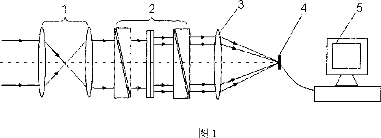
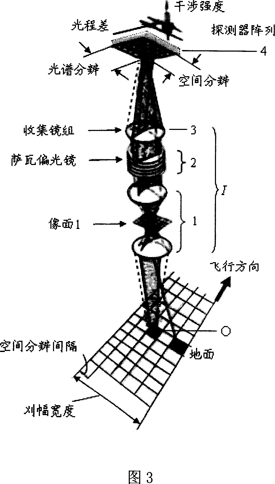
[0014] Referring to the accompanying drawings, the structure of the polarization interference imaging spectrometer includes a pre-telescope system 1, a polarization interferometer 2, an imaging mirror group 3, an area array detector 4, and a computer information image processing system 5. The signal output end of the area array detector 4 is connected with the signal input end of the computer signal processing system through a connection line.

[0015] The front telescopic system 1 is composed of a group of lenses, and its main function is to collect, collimate and reduce stray light from the radiation emitted by the target.

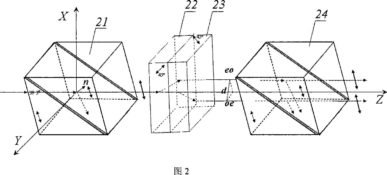
[0016] The structure of the polarization interferometer 2 is shown in FIG. 2 , which includes three parts: a ...


PUM


Abstract

The static birefringent polarizing interference imaging spectrometer consists of a pre-telescope system, a polarizing interferometer, an imaging lens set and an area array detector arranged coaxially and successively in the incident light direction, as well as a computerized signal treating system connected to the output of the area array detector. The polarizing interferometer consists of a polarizer, a Savart polariscope and an analyzer. The present invention adopts Savart polariscope as the transverse shearing beam splitter, and the advantages of infinitely far target, linear light path, simple structure, high stability, high S/N ratio, high resolution, etc.

Description

technical field [0001] The invention belongs to the technical field of optical imaging spectrometers, and relates to a remote sensing interference imaging spectrometer that can be used to simultaneously acquire target two-dimensional image, one-dimensional spectrum and polarization information. Background technique [0002] Imagers, spectrometers, and polarimeters in common concepts belong to three different classes of optical instruments. The shape and shadow image of the target can be obtained by using the imaging instrument, that is, the two-dimensional spatial information of the target; the spectrum of the target can be obtained by using the spectroscopic instrument to obtain the structure and chemical composition of the substance; the polarization information of the target can be obtained by using the polarimeter to know the object’s Attributes. Historically, these three categories of instruments developed independently. In the late 1980s, an interferometric imaging s...

Claims


Application Information

Patent Timeline
Patent Type & Authority Applications(China)
IPC IPC(8): G01J3/45G02B27/28
Inventor 张淳民赵葆常李英才
Owner XI AN JIAOTONG UNIV
Why Eureka
Try Eureka