
Permeability detecting device and saturated permeability detecting method fiber spread layer surface and thickness direction

A fiber lay-up and testing device technology, applied in measurement devices, permeability/surface area analysis, suspension and porous material analysis, etc. problem, to achieve the effect of high test efficiency, small measurement error and simple operation

Inactive Publication Date: 2007-10-10
BEIHANG UNIV
View PDF0 Cites 46 Cited by
  • Summary
  • Abstract
  • Description
  • Claims
  • Application Information

AI Technical Summary

Problems solved by technology

At present, there are many testing methods for unsaturated permeability. The main principle is to monitor the change of resin flow front and resin pressure or resin flow rate, and combine Darcy's law to calculate the value of permeability; while the research of saturated permeability mostly focuses on theoretical calculation. , there are few reports on the test method, which is mainly caused by the following points: (1) the network structure of the fiber is saturated with liquid before the test, and there is no flow front when it flows, so the usual unsaturated permeability test method cannot Application; (2) For composite parts with non-thin-walled structures, the resin will flow in multiple directions at the same time during the molding process, because the permeability is a tensor, and the permeability is different in different directions. This puts forward higher requirements for the design of the test mold; (3) A large number of weft-free fiber-free unidirectional prepregs are used in the hot pressing process, and the resin viscosity in this prepreg is very high or even appears It is solid and cannot be used as a test liquid. It is necessary to remove the resin and re-infiltrate the fiber with a liquid with low viscosity for testing. However, during the sample preparation process, the fiber weft direction has no binding force and is easy to scatter, resulting in great changes in the fiber network structure. The obtained permeability cannot reflect the permeability characteristics of the fiber reinforcement in the actual process; (4) Since the sample cannot be cut to be completely consistent with the size of the mold, the fluid flows in the edge of the gap between the fiber layer and the mold, which makes The measured value of the permeability is too high, and the fiber layup system used in the hot pressing process generally has a relatively high fiber volume fraction, the permeability is small, and the influence of the edge effect is greater

Method used


Image

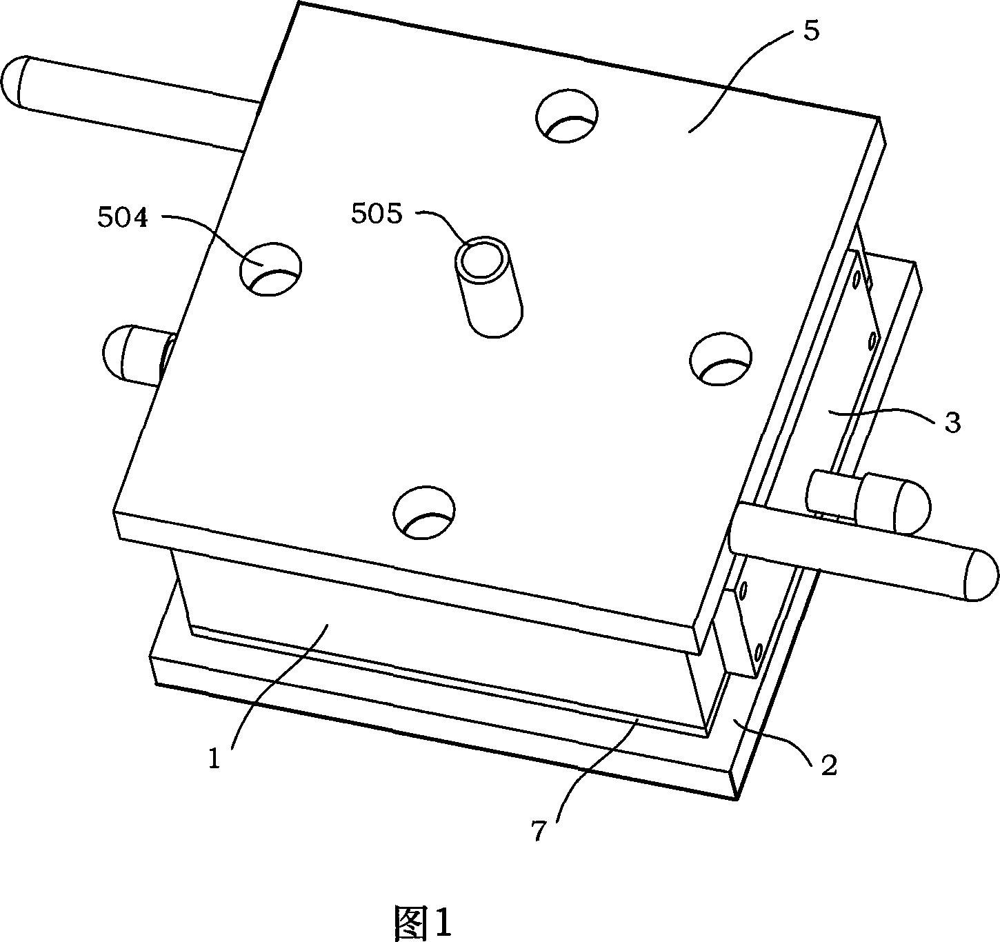
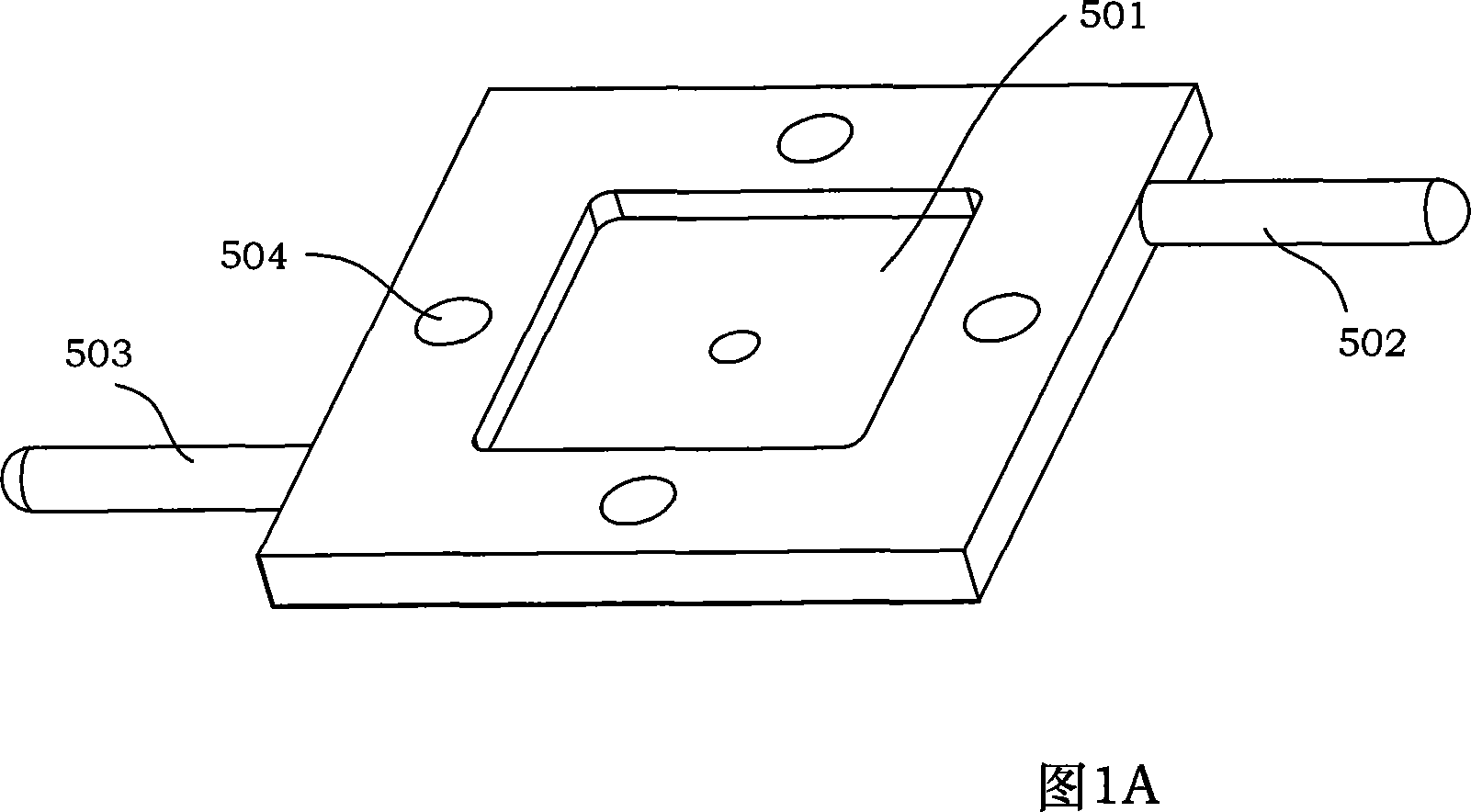
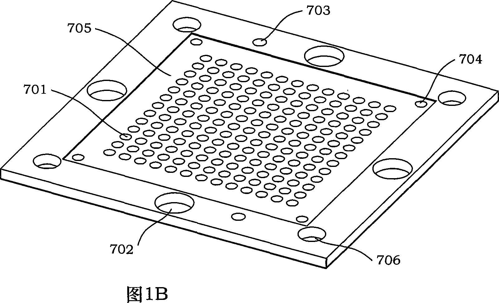
  • Permeability detecting device and saturated permeability detecting method fiber spread layer surface and thickness direction
  • Permeability detecting device and saturated permeability detecting method fiber spread layer surface and thickness direction
  • Permeability detecting device and saturated permeability detecting method fiber spread layer surface and thickness direction

Examples


Embodiment 1

[0078] S-2 high-strength glass fiber / epoxy E51 resin unidirectional prepreg is used as the test object. Cut the prepreg into 10×10cm 2 Finally, 40 layers are laid, and the laying method is one-way laying; after dissolving the epoxy E51 resin with acetone, soak the fiber laying layer with soybean oil, and then use a small press as a pressurizing device, and use soybean oil as a test liquid. Measure the fiber volume fraction in the range of 47% to 71% and the saturated permeability in the thickness direction of the fiber layer, the pressure P is adjusted in the range of 0.01 to 0.08MPa, the experimental temperature is 20°C, and the viscosity of soybean oil at this temperature is 0.06Pa s, the test results are shown in Table 1 and Table 2.

[0079] Fiber volume fraction (%)

[0080] Fiber volume fraction (%)

Embodiment 2

[0082] T700 carbon fiber plain weave fabric is used as the test object. Cut the fabric to 10×10cm 2 After laying 20 layers, the laying method is orthogonal laying; use a small press as the pressurizing equipment, and use corn steep liquor as the test liquid to measure the saturated permeability in the fiber laying layer and in the thickness direction when the fiber volume fraction is 60%. , the pressure P is adjusted within the range of 0.03-0.05MPa, the experimental temperature is 15°C, the viscosity of corn steep liquor at this temperature is 0.04Pa·s, and the saturated permeability in the fiber layup layer and in the thickness direction obtained from the test is 6.2×10 -12 m 2 and 7.8×10 -13 m 2 .

Embodiment 3

[0084] T300 carbon fiber twill fabric is used as the test object. Cut the fabric to 10×10cm 2 After laying 35 layers, the layering method is quasi-isotropic layering; a small press is used as a pressurized device, soybean oil is used as a test liquid, and the fiber layer and thickness direction saturation are measured when the fiber volume fraction is 55%. Permeability, the pressure P is adjusted in the range of 0.07-0.09MPa, the experimental temperature is 25°C, the viscosity of soybean oil at this temperature is 0.03Pa·s, and the saturated permeability in the fiber layer and thickness direction obtained from the test are 13.2× 10 -12 m 2 and 10.1×10 -14 m 2 .

[0085] V f


PUM

PropertyMeasurementUnit
Diameteraaaaaaaaaa
Viscosityaaaaaaaaaa
Viscosityaaaaaaaaaa

Abstract

A method for determining saturated penetration coefficient at thickness and inner surface directions of fiber fabric includes laying presoaked fiber fabric in test mould utilizing flow-dividing plate and four edge of mould cavity to fix network structure of fiber fabric, using solvent to remove off resin in presoaked fiber fabric, exerting pressure on fiber fabric to vary volume friction of fiber, erecting various accessories on said test mould to form different flow channels, using stopwatch and measuring cylinder to record relevant data and combining measured data with Darcy law for calculation out saturated penetration coefficient at thickness and inner surface direction on fiber fabric.

Description

technical field [0001] The present invention relates to a permeability testing device and its permeability testing method, more specifically, it refers to the testing method and permeability of the continuous fiber reinforced body in the ply layer and in the thickness direction of the resin-based composite material. test device. Background technique [0002] Permeability is a parameter that characterizes the ease of fluid flow in porous media under pressure. The greater the permeability, the smaller the flow resistance of the porous media to the fluid. In the manufacturing process of continuous fiber reinforced resin matrix composites, the permeability of the fiber is one of the important factors affecting the flow state of the resin. It is determined by the physical properties of the fiber and the internal structure of the fiber network, and is also related to the physical properties of the resin. , flow direction and the infiltration state of the resin on the fiber. In a...

Claims


Application Information

Patent Timeline
IPC IPC(8): G01N15/08G06F19/00
Inventor 张佐光李敏顾轶卓张大兴孙志杰李艳霞
Owner BEIHANG UNIV
Learn More