
Biomass fluid bed combustion device and combustion method

A combustion method and biomass technology, applied in the direction of combustion method, combustion type, incinerator, etc., can solve problems such as slagging and deposition, ash agglomeration, alkali metal corrosion of metal equipment, etc., to improve combustion efficiency, reduce combustion loss, The effect of increasing dwell time

Inactive Publication Date: 2007-10-24
SOUTHEAST UNIV
View PDF0 Cites 18 Cited by
  • Summary
  • Abstract
  • Description
  • Claims
  • Application Information

AI Technical Summary

Problems solved by technology

[0003] In recent years, with the increasingly widespread application of biomass combustion gasification power generation, fluidized bed technology is one of the main technical approaches for efficient biomass combustion, but various problems have also been encountered in the application of biomass fluidized bed combustion technology, such as solid incomplete Increased combustion loss, ash agglomeration, slagging and deposition due to low ash melting point, and alkali metal corrosion of metal equipment caused by biomass combustion are becoming more and more prominent
Although domestic and foreign are actively exploring to solve the problems of alkali metal deposition and corrosion in the process of biomass combustion, some methods to alleviate the problem of alkali metals have been proposed, including the use of additives, selection of suitable bed materials, removal of alkali metals before combustion, and the treatment of boilers. Optimizing the design, adjusting the combustion conditions, etc., but there is still no effective method to solve the deposition and corrosion problems in different biomass combustion processes, which brings great difficulties to the long-term stable and safe operation of commercial biomass combustion power generation equipment

Method used


Image

  • Biomass fluid bed combustion device and combustion method

Examples


Embodiment Construction

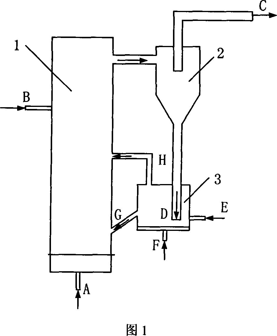
[0015] Below in conjunction with accompanying drawing, the present invention is described in detail, as shown in the figure, it comprises combustion reactor 1, respectively arranges an air inlet A and B at the bottom, upper middle part of combustion reactor 1, the top of combustion reactor and cyclone The separators 2 are connected, the top of the cyclone separator 2 is provided with a flue gas outlet C, and the lower end D of the cyclone separator 2 is passed into the pyrolysis gasification reactor 3, and the pyrolysis gasification reactor 3 is also provided with four ports, They are the air inlet F, the feed port E, the feed connecting pipe G connected to the combustion reactor 1, and the pyrolysis gas connecting pipe H. The feed connecting pipe G leads to the dense-phase combustion zone at the lower part of the combustion reactor 1, The pyrolysis gas connecting pipe H leads to the dilute-phase combustion zone in the middle or upper part of the combustion reactor 1 .

[0016...


PUM


Abstract

The present invention discloses a biomass fluidized-bed device and the method, the device includes a burning reactor equipped with at least one air inlet and a smoke gas outlet and a pyrolytic gasifying reactor which is connected with the burning reactor through pyrolytic gas connecting pipes and refeed connecting pipes, the pyrolytic gas connecting pipes are inserted into the upper or the middle of burning reactor, refeed connecting pipes are inserted into the lower of burning reactor, the pyrolytic gasifying reactor is also equipped with a gas inlet and a feeding mouth; the method is: first transmitting the biomass and addition agent into pyrolytic gasifying reactor to pyrolytic gasifying and generating carbonization pyrolytic gas; second transmitting the reacted pyrolytic gas into the dilute phase burning zone of burning reactor, transmitting the carbonization biomass into the dense phase burning zone of burning reactor to burn, the reacting temperature in pyrolytic gasifying reactor is 400-800deg.C and the reacting temperature in burning reactor is 600 -950deg.C, the method in the invention has characteristics of highly effective burning and effective preventing of base metal corrosion during the burning process.

Description

technical field [0001] The invention relates to a biomass combustion device and method, in particular to a circulating fluidized bed combustion device and a combustion method for effectively suppressing alkali metal corrosion in the biomass combustion process. Background technique [0002] my country is rich in biomass resources, but fossil energy is in short supply. In the 21st century, it will face the dual pressure of economic growth and environmental protection. Therefore, the development of biomass energy combustion and utilization technology is crucial to the establishment of a sustainable energy system and the promotion of the development of the national economy. and environmental protection are of great significance. [0003] In recent years, with the increasingly widespread application of biomass combustion gasification power generation, fluidized bed technology is one of the main technical approaches for efficient biomass combustion, but various problems have also b...

Claims


Application Information

Patent Timeline
IPC IPC(8): F23G5/30F23G5/027
Inventor 肖军沈来宏
Owner SOUTHEAST UNIV
Learn More