
Anti-explosion vacuum pressure varnished insulation apparatus and its technical method

A technology of vacuum pressure impregnation and insulation device, applied in the field of pressure vessels, can solve the problems of unsafe, unsmooth gas path, and high dielectric loss, and achieve the effects of improving service life, saving raw materials, and reducing dielectric loss.

Inactive Publication Date: 2007-10-31
WOLONG ELECTRIC NANYANG EXPLOSION PROTECTION GRP CO LTD
View PDF0 Cites 23 Cited by
  • Summary
  • Abstract
  • Description
  • Claims
  • Application Information

AI Technical Summary

Problems solved by technology

Although the current vacuum pressure impregnation equipment has good performance, it is impossible to avoid the influence of the insulating varnish remaining in the impregnation tank on the vacuum degree every time the vacuum is pumped, because the insulating varnish contains about 30% styrene or other diluents, and styrene or other diluents are flammable and explosive substances, the explosion limit range is 1-7%, and the spontaneous ignition point is 460°C
When there is more insulating varnish left in the varnish dipping tank, there will be more styrene or other diluents in the insulating varnish. When vacuuming, there will be more flammable and explosive gases entering the vacuum unit, especially benzene. Ethylene also has the characteristics of self-crosslinking and becoming a solid substance. The styrene or other diluents in the insulating varnish are pumped into the vacuum unit. Once solidified in the vacuum unit, it is easy to block the vacuum pump and cause the gas path to be blocked. And cause an explosion accident, so there is a great unsafe hidden danger
Vacuum pressure impregnation in the prior art does not fundamentally solve the remaining insulating varnish and solvent in the impregnation tank, resulting in high dielectric loss in the high-voltage motor winding coil after impregnation, which directly affects the service life of the high-voltage motor

Method used


Image

  • Anti-explosion vacuum pressure varnished insulation apparatus and its technical method
  • Anti-explosion vacuum pressure varnished insulation apparatus and its technical method

Examples


Embodiment Construction

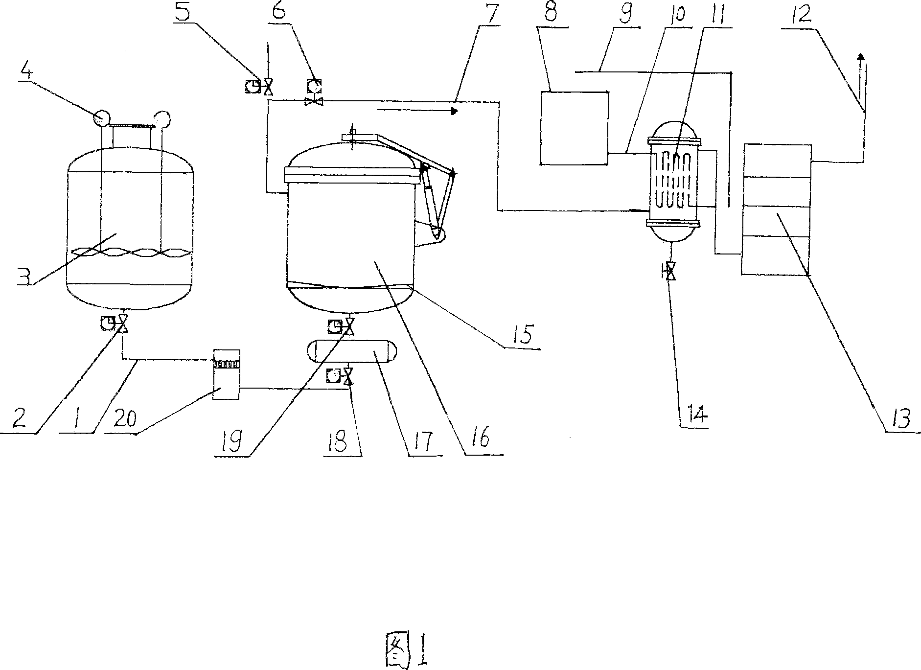
[0025] Referring to Figure 1, the labels in the figure are: paint delivery pipeline 1, paint delivery valve 2, paint storage tank 3, stirring motor 4, pressurized pneumatic valve 5, vacuum pneumatic valve 6, vacuum pipeline 7, refrigeration unit 8, water outlet Pipeline 9, water inlet pipe 10, condenser 11, sewage pipe 12, vacuum unit 13, drain valve 14, paint collection plate 15, paint dipping tank 16, paint collection tank 17, paint delivery and return valve 18, paint collection valve 19. Filter 20.

[0026] The explosion-proof vacuum pressure impregnation insulation device of the present invention is composed of a paint dipping tank 16, a paint storage tank 3, a vacuum unit 13, a refrigeration unit 8, a condenser 11, and a paint collection tank 17, wherein the condenser 11 is arranged in the paint dipping tank 16 On the vacuum pipe 7 between the vacuum unit 13, the condenser 11 is a tank body closed up and down, and a circulating cooling pipe is arranged in the tank body, a...


PUM


Abstract

The invention relates to explosion-proof vacuum pressure impregnated insulation device and its process which is used in high-tension motor winding loop impregnated insulation paint, it characterized in that: condensator connected with refrigerator is set on the vacuum tube between the impregnating vessel and vacuum set, and collecting vessel is set on bottom of the impregnating vessel, one end of the collecting vessel is connected with the impregnating vessel, the another end is connected with the paint pipelines of storing vessel via transferring valve and returning valve. Using the device and the process, the remained insulation paint and dissolvent in the impregnating vessel can be solved, when the vacuum set vacuumizes the impregnating vessel, the explosive fuel phenylethene deflocculating agent can not be sucked to the vacuum set to gel and jam, it possesses practical effects of explosion-proof, safe reliability, saving raw material.

Description

technical field [0001] The invention belongs to the technical field of pressure vessels, in particular to an explosion-proof vacuum pressure impregnated insulation device and a process method thereof for impregnating insulating varnishes for winding coils of high-voltage motors. Background technique [0002] The voltage generated by the generator can only be used through the grid transmission and sorting. Now, users combine the development needs of large drag and high power, and directly connect the motor to the transformer of 6Kv and above, which can reduce the loss of the line, and also reduce the re-investment of the low-voltage transformer and its auxiliary facilities. For this reason, high-voltage generators and electric motors of 6KV and above are popularized and applied in large areas. Since high-voltage motors are subject to high voltage and high current, in order to improve the withstand voltage level of high-voltage motor winding coils, vacuum pressure impregnatio...

Claims


Application Information

Patent Timeline
IPC IPC(8): H02K15/12H01F41/12B05D1/18H01B19/02
Inventor 尹默白双建田国群季泽伟张燕胥鹏涛姜艳
Owner WOLONG ELECTRIC NANYANG EXPLOSION PROTECTION GRP CO LTD
Learn More