
Medium frequency induction heating treatment method for steel pipe, petroleum well pipe and drill pipe

A heat treatment method and induction heating technology, applied in heat treatment furnaces, heat treatment equipment, furnace types, etc., can solve problems such as affecting the heating effect, automatic displacement of workpiece steel pipes or oil well pipes or drill pipes, and the surface brightness cannot be achieved. Achieve the effect of reducing production cost, low cost and less oxide scale

Active Publication Date: 2007-11-28
朱兴发
View PDF0 Cites 32 Cited by
  • Summary
  • Abstract
  • Description
  • Claims
  • Application Information

AI Technical Summary

Problems solved by technology

If the descaling device used is used in the heat treatment process of the workpiece steel pipe or oil well pipe or drill pipe, after the tempered steel pipe passes the descaling device on the roller table, the surface of the finished workpiece steel pipe or oil well pipe or drill pipe is bright and cannot achieve true colors
Such as the draining table used, the draining table is flat, it cannot automatically shift the workpiece steel pipe or oil well pipe or drill pipe, and it cannot automatically shift the workpiece steel pipe, oil well pipe or drill pipe on the draining table, After spraying and quenching, there is a small amount of accumulated water in the tube that cannot be drained away, so that the water will be brought to the tempering heating zone, which will not only affect the heating effect, but also water and water vapor will enter the tempering induction heating coil, affecting the induction heating coil service life

Method used


Image

  • Medium frequency induction heating treatment method for steel pipe, petroleum well pipe and drill pipe

Examples


Embodiment

[0037] The material storage platform is a slanted frame structure with an inclination of 2 to 5°. The workpiece steel pipe or oil well pipe or drill pipe rolls on the beam equipped with anti-noise nylon backing plate on the surface. The outlet end is designed with a material blocking device. Manual assistance during feeding can easily make the workpiece steel pipes or oil well pipes or drill pipes neatly arranged and distributed. The material storage platform is equipped with an eccentric wheel structure. For φ60~φ139.7, adjust the eccentric wheel at different angles to make the material turn over The device can only turn over one material at a time.

[0038] The workpiece steel pipe or oil well pipe or drill pipe is sent to the first station by the material rack of the storage table—aligned with the positioning roller table. The positioning roller table is composed of four rollers and is equipped with a material receiving switch. The rollers at both ends are The motor drives ...


PUM


Abstract

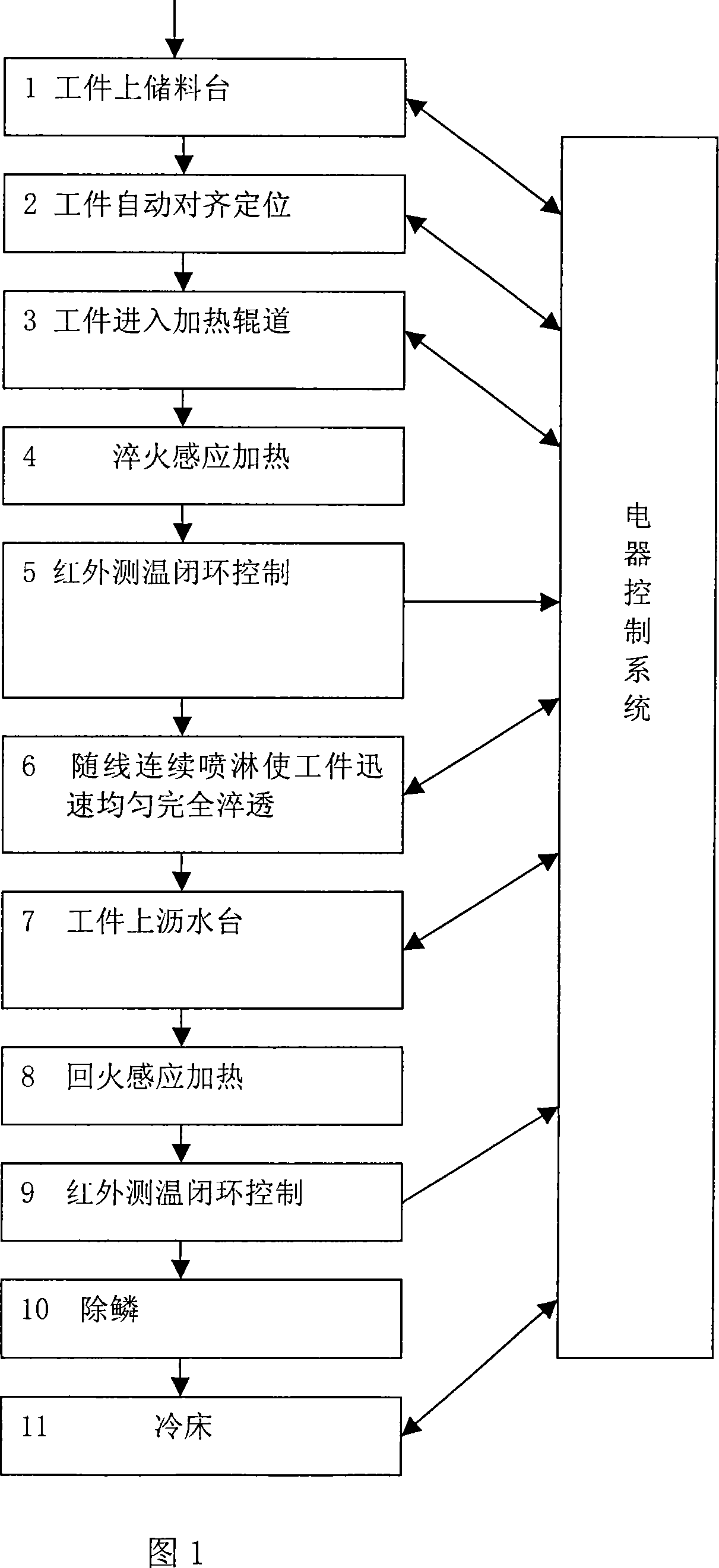
This invention provides a kind of main-frequency induction heating method using in the frequency treatment system of steel pipe and the tube and drill pipe of oil well. This method include put the work piece to the storage platform, the work piece automatic alignment and localization, the work piece enter the heating roller, quenching inducing heated, closed loop temperature control system, continuum spray ensure the work piece being uniformly quenched entire and quickly, the water stay in the work piece being ejected on the detearing platform, the work piece is heated by the temper inducing heater which controlled by the infrared thermometer controller, descaling device, and then enter the descaling device , the final is the cooling platform. The intermediate-frequency induction heater is using as the heating system, which is safe, no pollution and with little oxide scale. The heater roller ensure the work piece is heated uniformly and entirely, and after this process the work piece no need to be straightened which decrease the cost. The spray quenching equipment ensure the work piece could be uniformly quenched entire and quickly. The descaling device makes the surface of the work piece brightly. The detearing platform makes the work piece move automatically, which won' t influence the heating effect. And the water and steam could not enter the heating inducing loop either, which can increase the life of the loop..

Description

technical field [0001] The invention relates to a medium-frequency induction heating heat treatment method for steel pipes, oil well pipes and drill pipes, and belongs to the technical field of steel pipe heat treatment. Background technique [0002] The heat source in the existing heat treatment methods for steel pipes, petroleum oil well pipes and drill pipes is mainly gas (such as liquefied gas, natural gas, coal gas), and gas is used as the heating heat source in the heat treatment system. The main defect is that it is harmful to the environment. Pollution, potential safety hazards, many scales, high cost. In addition to using gas as a heating source in the prior art, there are defects in the used heating roller table, spray quenching device, descaling device, draining table and other equipment. For example, the used heating roller table cannot guarantee the workpiece steel pipe or oil well pipe or drill. The rod rotates itself during the heating process, and the workpi...

Claims


Application Information

Patent Timeline
IPC IPC(8): C21D9/08C21D1/18C21D1/42
CPCY02P10/20Y02P10/25
Inventor 朱兴发
Owner 朱兴发
Learn More