
Method for detecting DNA by stacking hybridization fluorescent amplify magnetic separation

A magnetic separation and fluorescence technology, applied in the field of DNA detection, can solve the problems of cumbersome condition optimization, false positives, false negatives, etc., and achieve the effect of rapid on-site sampling

Inactive Publication Date: 2007-12-05
东莞市才智坊新材料有限公司
View PDF0 Cites 11 Cited by
  • Summary
  • Abstract
  • Description
  • Claims
  • Application Information

AI Technical Summary

Problems solved by technology

[0009] The above-mentioned development of nanoscience and technology has undoubtedly promoted the development of ultra-sensitive recognition technology for biological macromolecules, but overall it is still in the early stages of development, and many problems have not yet been resolved. For example, the high-noise background of immobilized molecular beacons involves the interface Many issues in surface chemistry: stability of nanoparticles, intermolecular interactions, influence of interfaces on molecular motion, steric effects and assembly density of immobilized label molecules and the influence of linker molecule / group length on biomacromolecule recognition etc., it is urgent for people to conduct in-depth discussions
However, due to the need for an amplification process, the optimization of conditions is cumbersome, and it is very sensitive to the influence of reagent quality and environment, and sometimes false positive or false negative results may occur. Therefore, the overall development trend is to use PCR technology and actively explore PCR-free methods. Highly sensitive analytical methods where amplification by nanoparticles is preferred by researchers

Method used


Image

  • Method for detecting DNA by stacking hybridization fluorescent amplify magnetic separation
  • Method for detecting DNA by stacking hybridization fluorescent amplify magnetic separation

Examples


Embodiment Construction

[0024] Below in conjunction with accompanying drawing and specific embodiment the present invention is described in further detail:

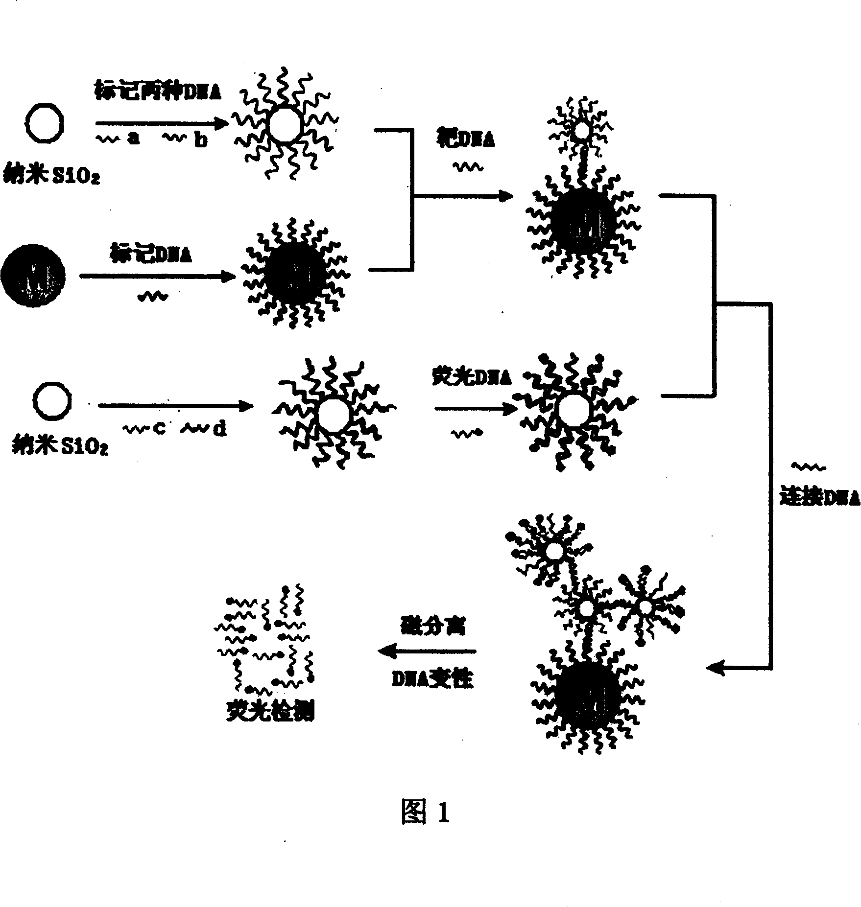
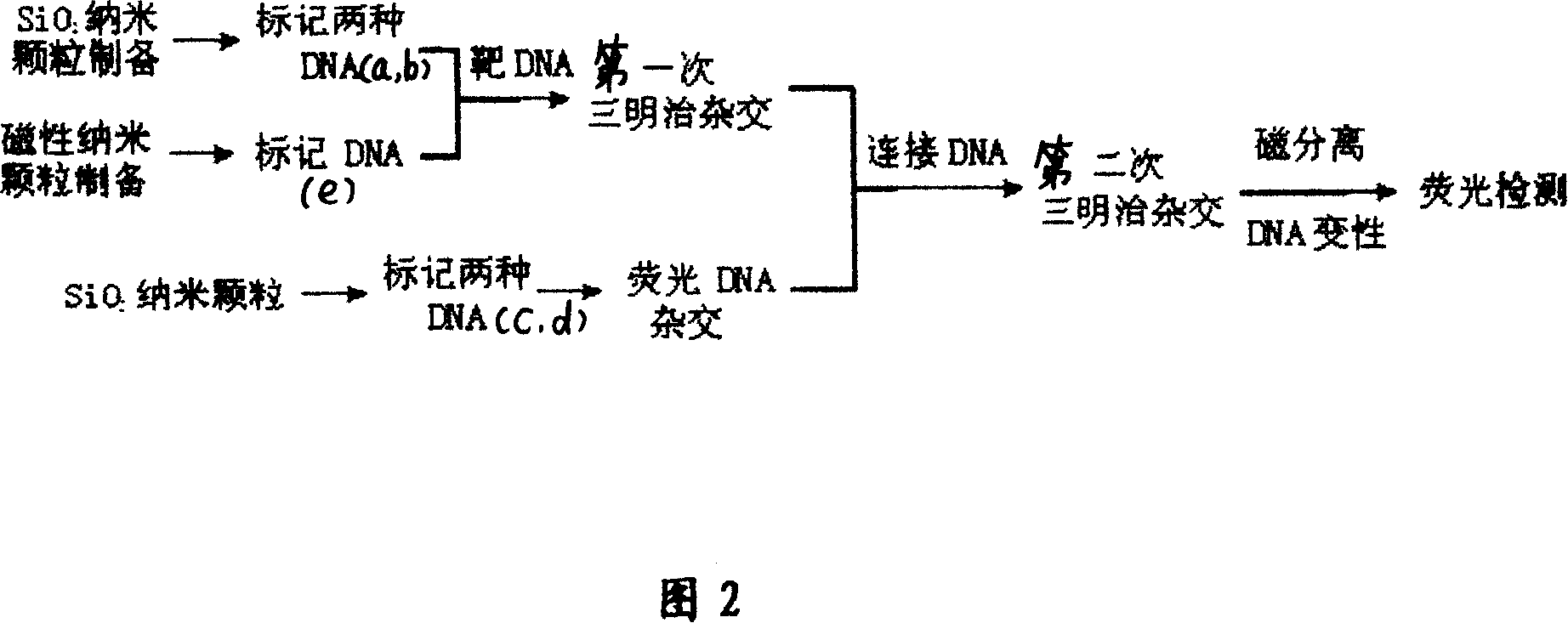
[0025] See Figures 1 and 2 for the principle diagrams of cascade amplification DNA detection. SiO 2 Two kinds of DNA with different sequences a and b are marked on the nanoparticle at the same time, wherein sequence a is completely positively matched with one end of the connecting DNA, and sequence b is completely positively matched with one end of the target sequence DNA. The amount of marking of sequence a is much larger than that of sequence b. Another DNA sequence e is marked on the surface of the magnetic nanoparticle, and its sequence is completely positively matched with the other end of the target DNA. Two kinds of nanoparticles modified with DNA hybridize with the target DNA for the first time, and the sequences b and e on the surface of the nanoparticles form a “sandwich” hybridization structure with the target sequence. At this time, ...


PUM


Abstract

The invention discloses a laminated crossed fluorescent amplified magnetic separating and detecting method of DNA, which comprises the following steps: marking DNA of two different sequences a and b on the SiO2 nanometer particle simultaneously; marking DNA on the magnetic nanometer particle surface of sequence e; crossing one end of target DNA and the DNA of the sequence b on the SiO2 nanometer particle; crossing the other end of target DNA and DNA of sequence e on the magnetic nanometer particle; marking the DNA of two different sequences c and d on the SiO2 nanometer particle simultaneously; crossing DNA of SiO2 nanometer particle on the sequence c and fluorescent DNA; finishing the first sandwich crossing; crossing the DNA of first sandwich crossed SiO2 nanometer particle on the sequence a and one end of connected DNA; crossing the other end of DNA and the DNA on the nanometer particle on the sequence d after fluorescent cross; cleaning the product after the second sandwich cross through magnetic separation; removing residual fluorescent molecule and non-specific adsorption; denaturizing the DNA after the second sandwich cross; proceeding fluorescent detection for the unlinked fluorescent DNA.

Description

【Technical field】 [0001] The invention relates to a method for detecting DNA. 【Background technique】 [0002] Since Watson and Crick created the double helix structure of biological genetic molecule deoxyribonucleic acid (DNA) and established the molecular mechanism of biological genetic genes in 1953, the identification and sequencing of DNA molecules have been widely recognized by people. focus on. In 1990, the United States formulated the world's largest genetic research program "Human Genome Project". With the publication of the draft human gene, people are conducting in-depth research on the post-genome project. For this reason, research on biochips and biosensors has been launched internationally. upsurge. Genes control the birth, aging, sickness and death process of human life. With the understanding of genes and cancer and other gene-related diseases, the detection of susceptible species and gene mutations at the molecular level is of great significance for the tre...

Claims


Application Information

Patent Timeline
IPC IPC(8): G01N21/64C12Q1/68
Inventor 聂立波贺全国陈洪何农跃
Owner 东莞市才智坊新材料有限公司
Learn More