Optical fiber holding apparatus and fiber laser processing apparatus

A holding device and optical fiber technology, applied in lasers, laser welding equipment, laser parts, etc., can solve the problems of optical fiber degradation, fluctuation of laser oscillation characteristics, damage, etc., to reduce deterioration and damage, improve laser characteristics, and maintain performance. and the effect of heat dissipation

Inactive Publication Date: 2007-12-05
MIYACHI TECHNOS CORP
View PDF0 Cites 10 Cited by
  • Summary
  • Abstract
  • Description
  • Claims
  • Application Information

AI Technical Summary

Problems solved by technology

Such external light not only exerts a thermal shock on the core end face, but also propagates through the fiber as anomalous light, causing fluctuations in laser oscillation characteristics, and deterioration and damage of the fiber

Method used


Image

  • Optical fiber holding apparatus and fiber laser processing apparatus
  • Optical fiber holding apparatus and fiber laser processing apparatus
  • Optical fiber holding apparatus and fiber laser processing apparatus

Examples


Embodiment Construction

[0028] Preferred embodiments of the present invention will now be described with reference to the accompanying drawings.

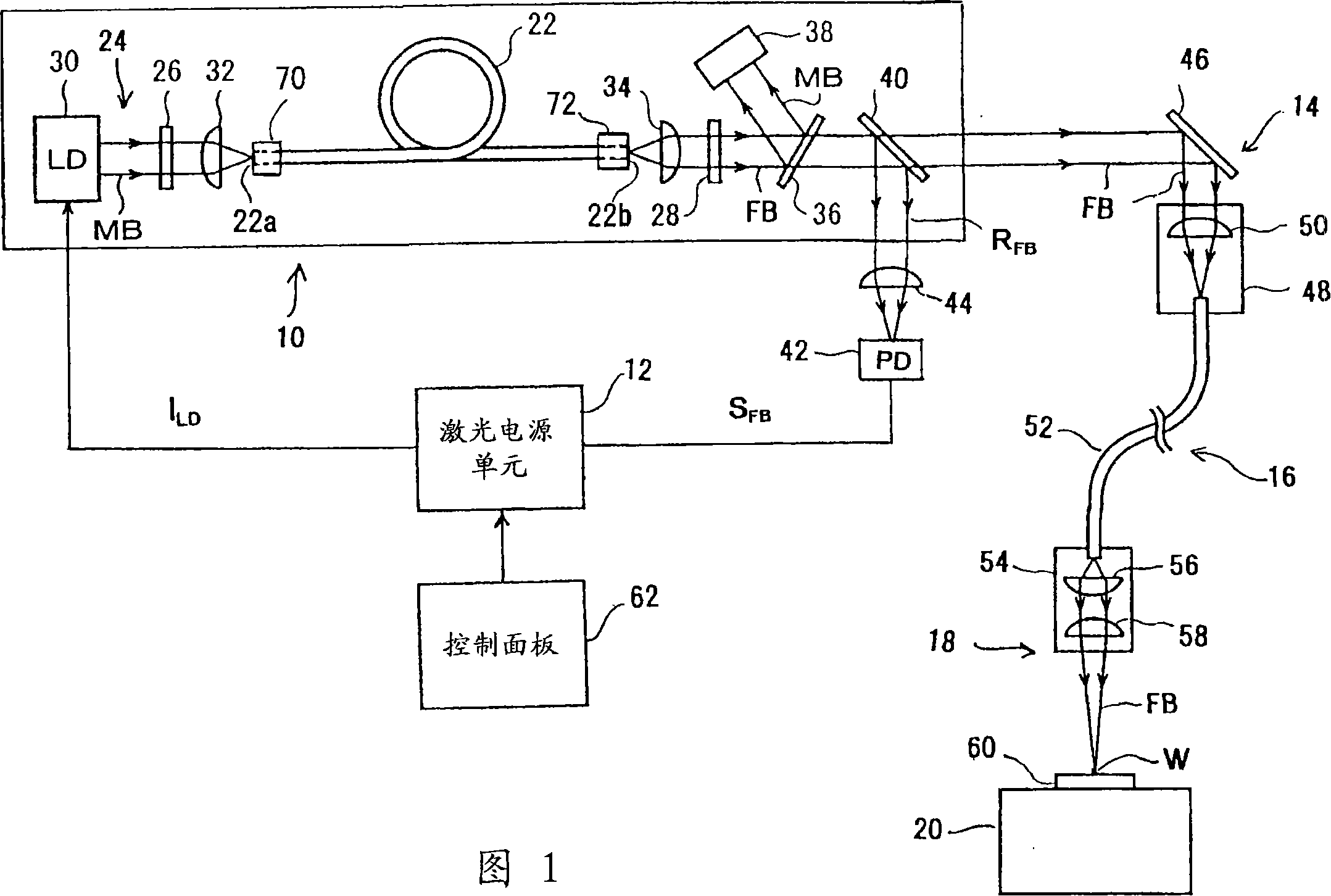
[0029] FIG. 1 shows the configuration of a fiber laser processing apparatus according to one embodiment of the present invention. The fiber laser processing device includes a fiber laser oscillator 10 , a laser power supply unit 12 , a laser incident unit 14 , an optical fiber transmission system 16 , a laser emitting unit 18 and a processing table 20 .

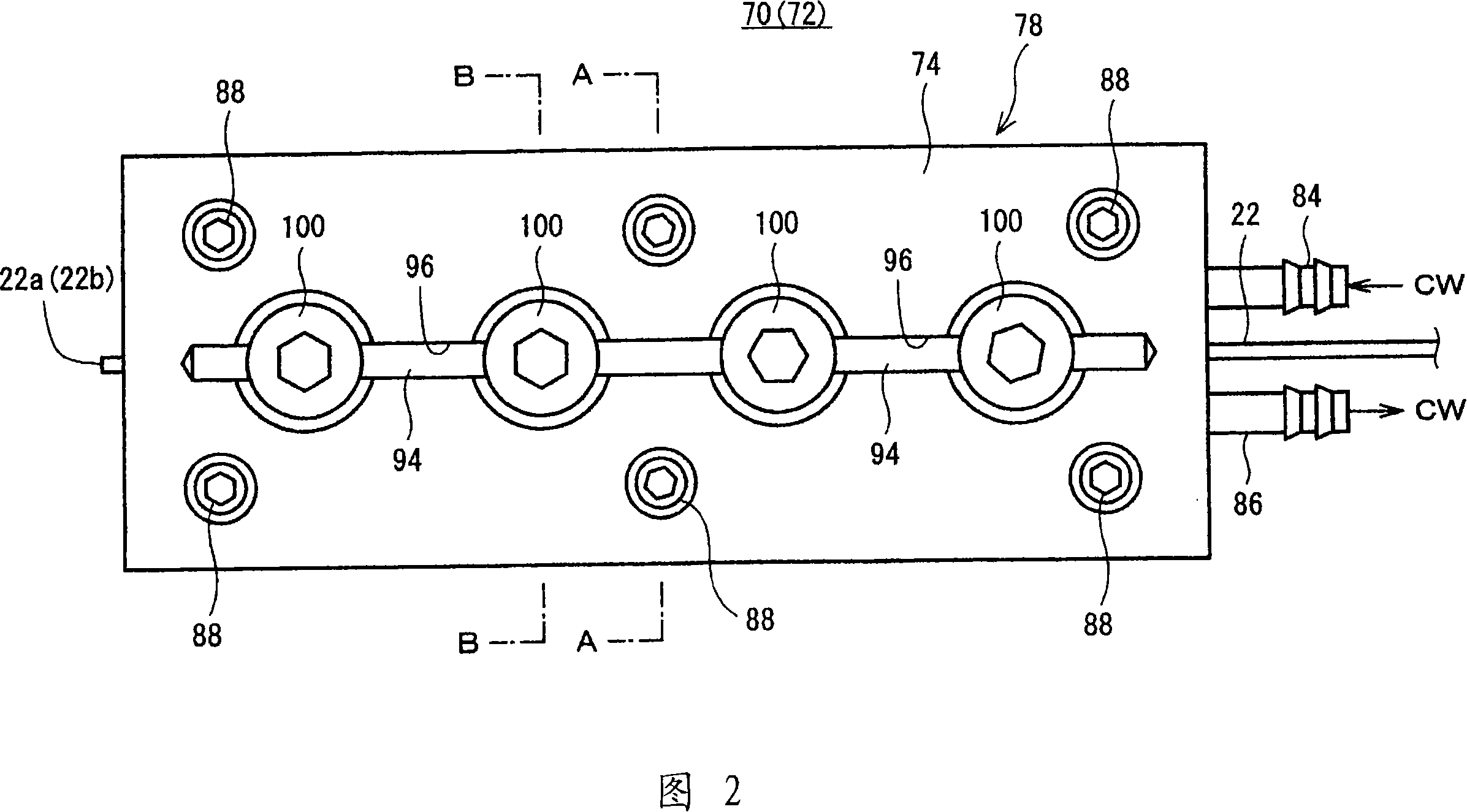
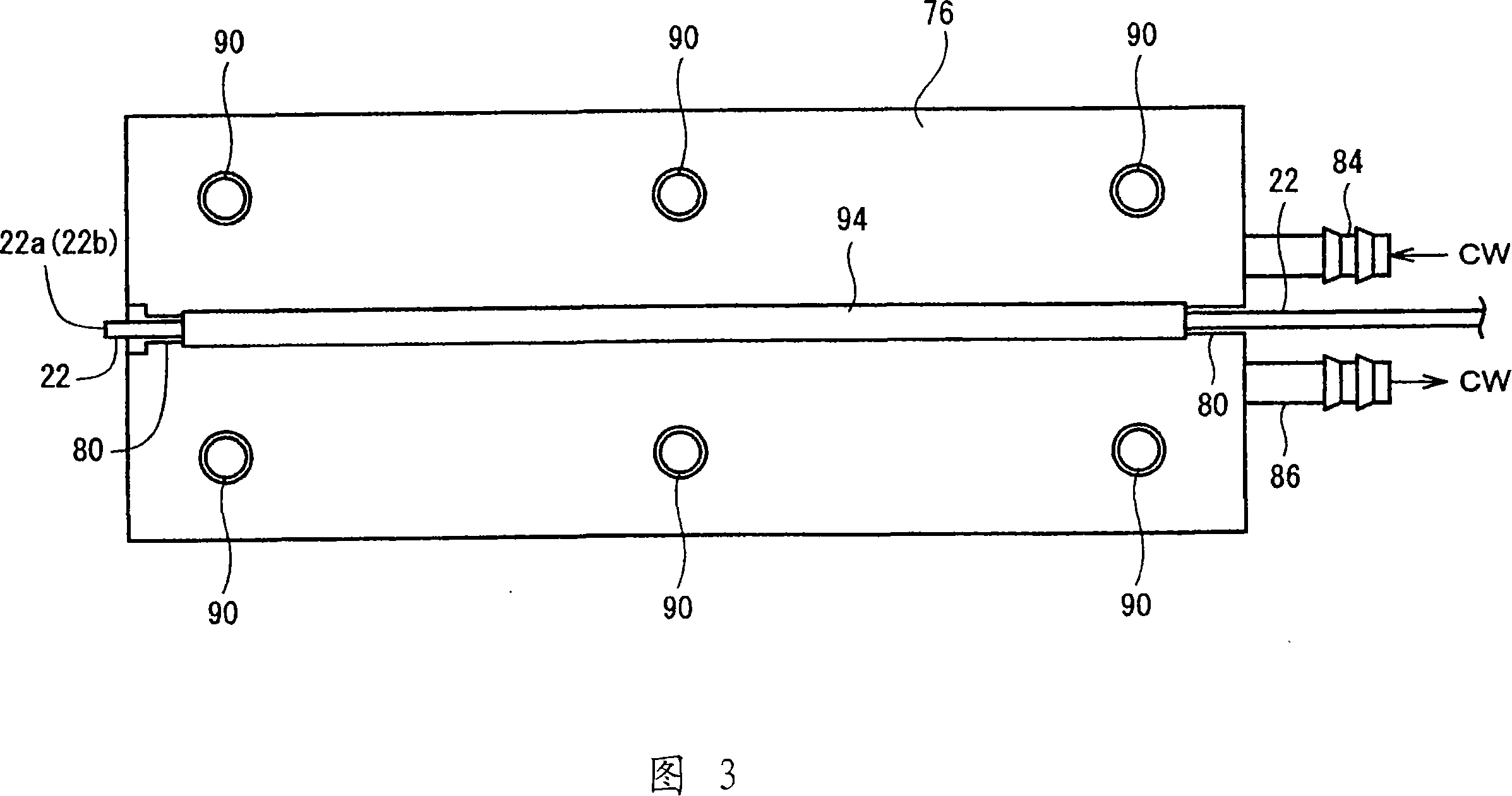
[0030] The fiber laser oscillator 10 has an oscillating fiber (hereinafter referred to as "oscillating fiber") 22, a photoelectric excitation unit 24 that sends excitation light MB excited to the end face of the oscillating fiber 22, and a pair of optically opposite optical fibers on both sides of the oscillating fiber 22. Optical resonator mirrors 26 and 28 . Both ends of the oscillation fiber 22 are held by fiber holders 70 and 72, respectively. The fiber holders 70 and 72 constitute the fiber holder ...


PUM

PropertyMeasurementUnit
lengthaaaaaaaaaa
lengthaaaaaaaaaa
refractive indexaaaaaaaaaa

Abstract

One end of an optical fiber for oscillation (22) is held in a holding groove (80) having a V-shaped section, which holding groove (80) is formed on the upper face of a lower block (76). On an upper block (74), a slit (96) is formed opposite the holding groove (80) of the lower block (76). A sapphire rod (94) can be inserted from above into the slit (96), and is guided vertically in a slidable manner in the slit. The sapphire rod (94) is brought in contact with the upper face of the optical fiber for oscillation (22), and is supported to be slidable over both side inner wall surfaces at the lower end of the slit (96). Bolts (100) are used to adjust a spring pressure of a compressive coil spring (102), which in turn adjusts a press force against the optical fiber for oscillation (22).

Description

technical field [0001] The present invention generally relates to an optical fiber holding device for holding an optical fiber, and in particular, relates to an optical fiber holding device for a fiber laser and an optical fiber laser processing device using the optical fiber holding device. Background technique [0002] In recent years, fiber laser processing devices have been used in practice. A fiber laser processing device emits laser light generated by a fiber laser onto a workpiece to perform desired laser processing on the workpiece. [0003] Generally, according to a fiber laser used in a fiber laser processing apparatus, an optical fiber for oscillation having a core doped with a rare earth element is optically disposed between a pair of optical resonator mirrors , the core of the optical fiber is optically excited, so that the oscillating light with a predetermined wavelength is axially emitted from the end face of the core and oscillates and amplifies back and fo...

Claims


Application Information

Patent Timeline
Patent Type & Authority Applications(China)
IPC IPC(8): G02B6/36G02B6/38B23K26/00G02B6/42H01S3/02
CPCH01S3/067H01S3/1312G02B6/4296G02B6/425G02B6/3616H01S3/06704H01S3/06729G02B6/423B23K26/10B23K26/02G02B6/36
Inventor 松田恭岛田秀宽赤城正幸
Owner MIYACHI TECHNOS CORP
Why Eureka
Try Eureka