
Method and device for depositing a protective layer during an etching procedure

A protective layer and etching technology, which is applied in the direction of electrical components, semiconductor/solid-state device manufacturing, circuits, etc., can solve problems such as increasing process complexity

Inactive Publication Date: 2007-12-05
QIMONDA
View PDF0 Cites 5 Cited by
  • Summary
  • Abstract
  • Description
  • Claims
  • Application Information

AI Technical Summary

Problems solved by technology

[0005] All these methods increase the complexity of the process

Method used


Image

  • Method and device for depositing a protective layer during an etching procedure
  • Method and device for depositing a protective layer during an etching procedure
  • Method and device for depositing a protective layer during an etching procedure

Examples


Embodiment Construction

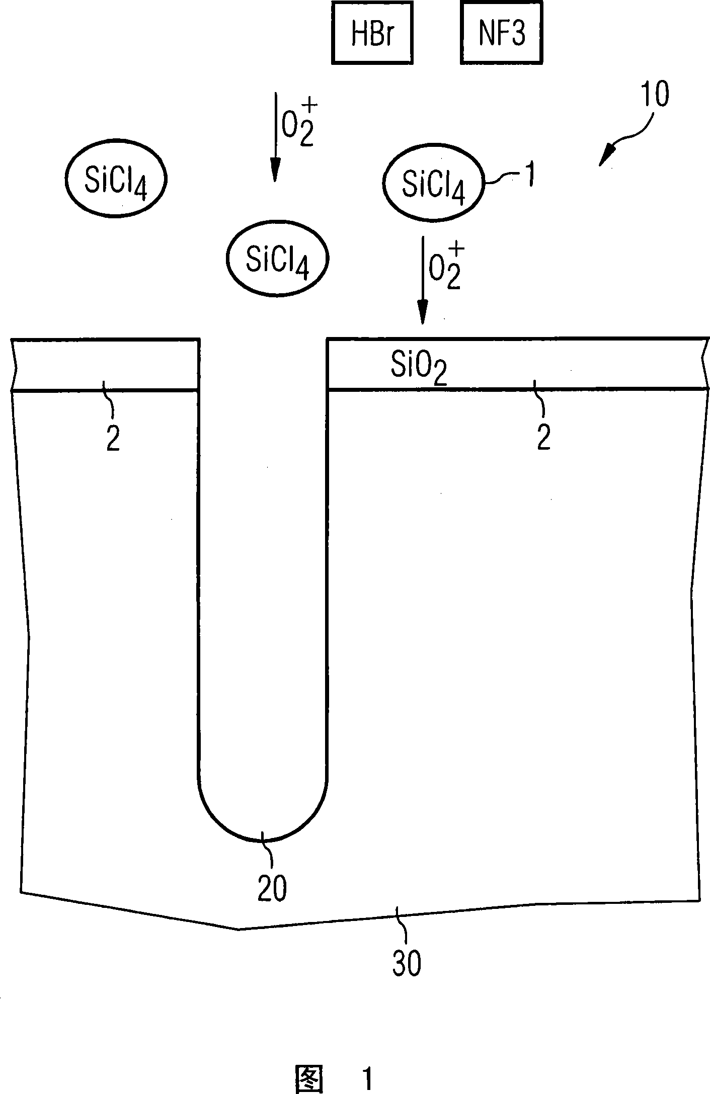
[0015] FIG. 1 schematically shows a trench structure 20 in a material 30 . It is assumed here that the material 30 is a silicon wafer used to manufacture DRAM chips. The silicon wafer has a diameter of 300 mm.

[0016] The trench structure 20 here is a deep trench structure of a memory cell with an aspect ratio of about 55.

[0017] By dry etching step with plasma 10, with HBr, NF 3 The deep trench structure 20 is introduced into the material 30 as an etching medium. Since the etching of the deep trench structure 20 takes a relatively long time, the surfaces of the horizontal layers on the left and right of the deep trench structure 20 in FIG. 1 will be removed through this etching process.

[0018] According to the embodiment of the invention shown here, a precursor 1 is added to the plasma 10 in a targeted manner, which precursor is compatible with the constituents in the plasma 10 (O 2 ) react together, so that the protective layer 2 is formed on the material 30 in a pl...


PUM


Abstract

A device and method for depositing a protective layer on a material during a plasma etching procedure in the course of fabricating semiconductor components, in particular in the course of fabricating DRAM chips, characterized in that the plasma(10) has at least one precursor(1) which, during the plasma etching procedure, together with a constituent of the plasma(10) at least partially forms a protective layer(2) on a planar region of the material(30) and, characterized by a means for feeding the at least one precursor(1) into the plasma(10), in which case, by means of the at least one precursor(1), during the plasma(10) etching procedure, together with a constituent of the plasma, a protective layer(2) can at least partially be deposited on a planar region of the material(30).

Description

technical field [0001] The invention relates to a method according to the preamble of claim 1 and an apparatus according to the preamble of claim 13 . Background technique [0002] In the process of patterning materials in the semiconductor industry, etching processes, especially dry etching processes, are commonly used to pattern substrates. Plasma etching is a typical dry etching process in which plasma is used to remove materials. Plasma etching includes, for example, reactive ion etching (RIE), in which, in addition to ion bombardment, the reactive components of the gas atmosphere used also play a role. In particular anisotropic etching can be achieved by reactive ion etching. Plasma etching also includes ICP (Inductively Coupled Plasma) methods. Combinations of MERIE (MERIE magnetically enhanced RIE), RIE, ECR (electron cyclotron resonance), helicon source and ICP methods are also possible. [0003] For example, a typical application of the dry etching process is to...

Claims


Application Information

Patent Timeline
Patent Type & Authority Applications(China)
IPC IPC(8): H01L21/00H01L21/3065
CPCH01L21/3065H01L21/3085
Inventor A·亨克S·韦格
Owner QIMONDA
Learn More