Semiconductor device and its manufacturing method

A manufacturing method and semiconductor technology, which is applied in the direction of semiconductor devices, semiconductor/solid-state device parts, electric solid-state devices, etc., can solve the problems of thicker semiconductor devices, higher costs, and increased thickness of semiconductor devices, so that the manufacturing process will not complicating effect

Inactive Publication Date: 2008-01-16
PANASONIC CORP
View PDF4 Cites 2 Cited by
  • Summary
  • Abstract
  • Description
  • Claims
  • Application Information

AI Technical Summary

Problems solved by technology

[0009] In the mounting technique described in Patent Document 1, the thickness of the semiconductor device becomes thicker due to the wiring height of the wire bonding and the thickness of the resin used to seal the lead portion
In addition, since the bonding wires also extend in the lateral direction, it is not necessarily possible to achieve the effect of reducing the area compared to the case where the semiconductor chips are arranged in a planar manner.
[0010] In addition, in the mounting technology described in Patent Document 2 or Patent Document 3, a dedicated relay substrate (relay component) occupies a relatively large area, so that the occupied area of ​​the semiconductor device is correspondingly enlarged in the lateral direction. In this case, compared with the case where the semiconductor chips are arranged planarly, the effect of reducing the area may not be obtained.
In addition, since the thickness of the dedicated interposer (interconnect part) increases the thickness of the semiconductor device accordingly, it cannot be asserted that a sufficient effect of volume reduction can be obtained, and there may be cases where the use of the interposer (interconnect part) Relay parts) resulting in higher costs
[0011] As described above, in the conventional mounting technology, when stacking (or three-dimensionally mounting) a plurality of semiconductor chips, compared with the case of arranging each chip in a planar manner, the effect of area and volume reduction or cost there are some deficiencies

Method used


Image

  • Semiconductor device and its manufacturing method
  • Semiconductor device and its manufacturing method
  • Semiconductor device and its manufacturing method

Examples


Embodiment approach 1

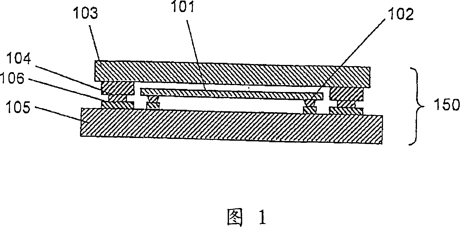
[0092] FIG. 1 is a cross-sectional view of a semiconductor device showing the basic structure of the semiconductor device of the present invention.

[0093] As shown in the figure, the semiconductor device 150 is three-dimensionally mounted with two semiconductor chips 101 and 103 by flip-chip mounting.

[0094] That is, on the first semiconductor chip (lower semiconductor chip) 101, a bump electrode (a low-level electrode: hereinafter referred to as a first electrode) 102 formed by metal plating or the like is formed, and the first electrode 102 It is directly connected to a predetermined wiring pattern 106 formed on the substrate 105 . That is, the first semiconductor device is mounted on the main surface of the substrate 105 by flip-chip mounting.

[0095] Similarly, a tall electrode 104 (hereinafter referred to as a second electrode) is formed on the second semiconductor chip 103 , and the second electrode 104 is directly connected to a predetermined wiring pattern 106 fo...

Embodiment approach 2

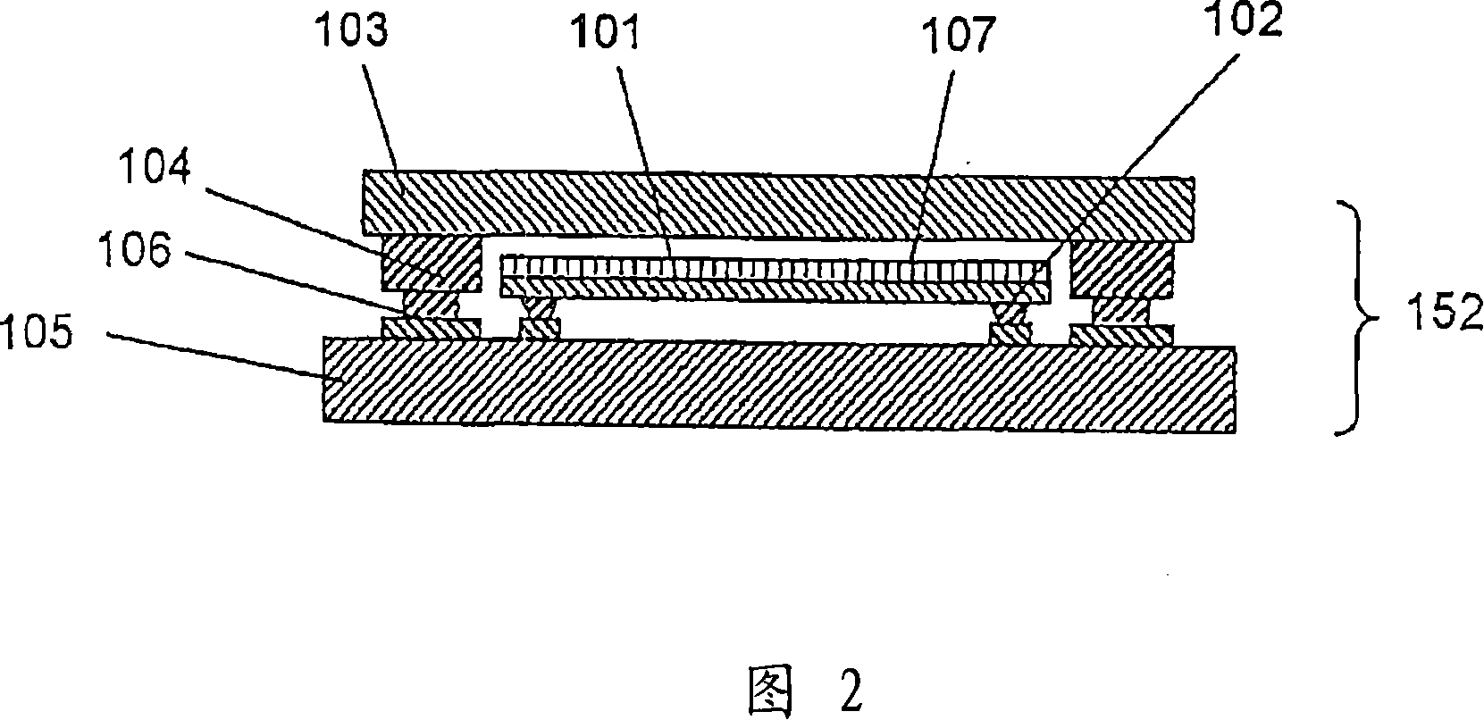
[0120] 4 is a cross-sectional view of a semiconductor device showing another example of the semiconductor device of the present invention (an example in which a first semiconductor chip and a second semiconductor chip are integrated). In FIG. 4 , the same reference numerals are assigned to the same parts as those in the illustrations described above, and the description of the common parts will be omitted. This also applies to the illustrations below.

[0121] In the aforementioned embodiments, the two semiconductor chips are flip-chip mounted separately, but in this embodiment, the two semiconductor chips (101, 103) are first bonded, and then flip-chip mounted. The integrated semiconductor chips are mounted on the substrate 105 together.

[0122] That is, in the above-mentioned embodiments, the first semiconductor chip 101 and the second semiconductor chip 103 are not in contact or in a state of not being closely attached, but in this embodiment, the upper surface of the fir...

Embodiment approach 3

[0134] 5 is a cross-sectional view of a semiconductor device showing another example of the semiconductor device of the present invention (an example in which the entire semiconductor device is sealed with resin).

[0135] In the present embodiment, the package structure is formed by sealing the bare chips (101, 103) with resin, thereby improving the water resistance or environment resistance of the semiconductor device. As shown in FIG. 5, a resin sealing body 109 for sealing the entire semiconductor device is provided on a semiconductor device 158 of this embodiment (the other structures are the same as those in FIG. 1).

[0136] The sealing resin 109 is composed of epoxy resin, polyimide resin, acrylic resin, silicone resin, etc. with high heat resistance (glass transition temperature: 120-180°C), and preferably does not contain corrosion-inducing components such as halogen and organic phosphoric acid. . In addition, the curing temperature of the sealing resin 109 is 100 t...


PUM

PropertyMeasurementUnit
Thicknessaaaaaaaaaa
Heightaaaaaaaaaa
Thicknessaaaaaaaaaa

Abstract

The thickness and occupied area are reduced compared with conventional methods when semiconductor chips are three-dimensionally arranged, low-cost mounting is realized without using any other components, and the manufacturing process of the semiconductor device is simplified. A flip-chip mounting structure in which a first semiconductor chip (101) thinned by back-grinding and a substrate (105) are directly connected to a wiring pattern (106) through bump electrodes (102) is fabricated. For example, an electrode (104) higher than the sum of the thickness of the first semiconductor chip (101) and the electrode (102) is formed on a second semiconductor chip (103) and connected directly to the wiring pattern (106) on the substrate (105), thus providing a most-compact, three-dimensional semiconductor mounted device.

Description

technical field [0001] The present invention relates to a semiconductor device formed by three-dimensionally mounting a plurality of semiconductor chips on a common substrate by flip-chip mounting and a method of manufacturing the same. Background technique [0002] In order to achieve high density and miniaturization of semiconductor devices, semiconductor chips are often mounted on substrates by flip-chip mounting. Flip-chip mounting is a mounting method in which a bare semiconductor chip without a package structure is mounted in a flip-chip state on a wiring pattern of a substrate. [0003] Conventionally, there has been proposed a mounting structure in which another semiconductor chip is laminated on one flip-chip mounted semiconductor chip (or another semiconductor chip is three-dimensionally arranged on one semiconductor chip), so that the mounting area can be minimized. shrinkage (Patent Documents 1 to 3). [0004] In Patent Document 1, another semiconductor chip is...

Claims


Application Information

Patent Timeline
IPC IPC(8): H01L25/065H01L25/07H01L25/18
CPCH01L2225/06517H01L2225/06555H01L25/0657H01L2924/15151H01L2224/73204H01L2224/16225H01L23/552H01L2225/06582H01L2924/09701H01L2224/32225H01L2225/06527H01L2224/32145H01L2224/73253H01L2224/05573H01L2224/05568H01L2224/05644H01L2224/05647H01L2224/05655H01L2924/00014H01L2224/0554H01L2224/83192H01L2924/00H01L2224/05599H01L2224/0555H01L2224/0556
Inventor 川端理仁冨士原义人
Owner PANASONIC CORP
Why Eureka
Try Eureka