Laser beam injecting optical device for optical fiber

An optical device and laser technology, applied in optics, optical components, fluorescence/phosphorescence, etc., can solve the problem of not being able to transmit laser light, and achieve the effect of suppressing air breakdown

Inactive Publication Date: 2008-01-23
KK TOSHIBA +1
View PDF2 Cites 11 Cited by
  • Summary
  • Abstract
  • Description
  • Claims
  • Application Information

AI Technical Summary

Problems solved by technology

[0009] However, in order to avoid damage to the incident end face and inside of the optical fiber, in the configuration in which the laser focus generated by the focusing lens is formed on the front of the optical fiber, the pulsed laser beam with a peak power of several MW or more is focused by the focusing lens and incident on the core diameter φ1mm. When the optical fiber is used, although stable laser light can be transmitted after the start of laser oscillation, as time goes by, the air near the focus of the laser light generated by the focusing lens gradually becomes ionized
Therefore, there is a problem that air breakdown occurs frequently, and stable laser light cannot be transmitted due to the influence of plasma generated by air breakdown.

Method used


Image

  • Laser beam injecting optical device for optical fiber
  • Laser beam injecting optical device for optical fiber
  • Laser beam injecting optical device for optical fiber

Examples


Embodiment Construction

[0018] Hereinafter, an embodiment of the present invention will be described with reference to the drawings.

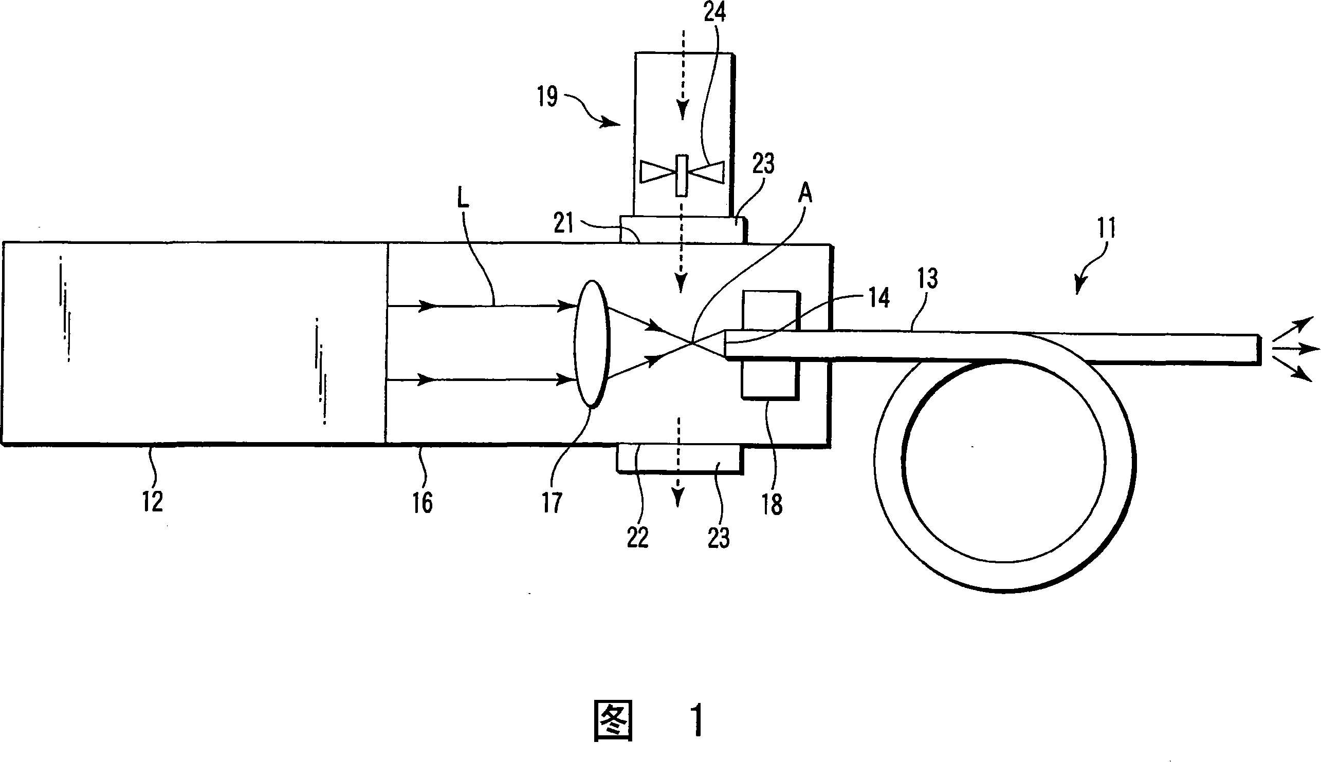
[0019] As shown in FIG. 1 , the laser incident optical device 11 for an optical fiber uses the pulsed laser light L generated by the laser oscillator 12 , which is a solid-state laser oscillator with a peak power of about 1 MW to 25 MW, so that the optical fiber 13 is not damaged. Furthermore, it is possible to transmit the stable laser light generated by the optical fiber 13 and enter the incident end face 14 of the optical fiber 13 having a predetermined core diameter and cladding thickness. In addition, if the peak power of the laser light L is greater than 25MW, the optical fiber 13 with a core diameter of about φ1mm may be damaged, so it is preferably about 25MW or less.

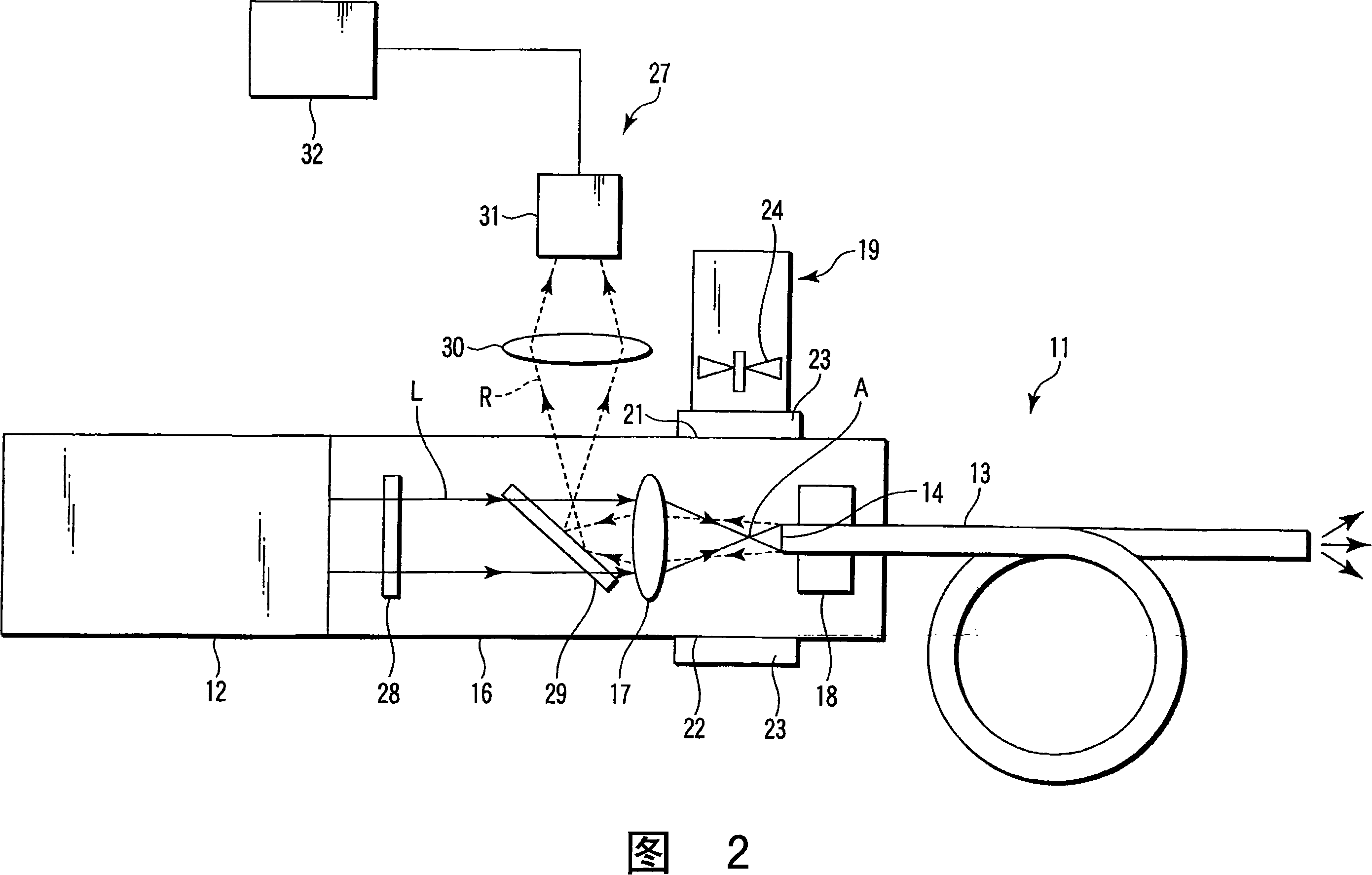
[0020] This optical fiber laser incident optical device 11 has a shielded container 16. At one end of the shielded container 16, a laser oscillator 12 outputting laser light L is arranged in th...


PUM


Abstract

In a shielding case, a condenser lens condenses a laser beam output by a laser oscillator to inject the laser beam into an entrance end face of an optical fiber disposed posterior to a focusing point of the laser beam. Ventilation of an ambient gas in the shielding case is carried out by ventilating means, and the ambient gas bringing about ionization in the vicinity of the focusing point of the laser beam is eliminated, thereby preventing the outbreak of air breakdown.

Description

[0001] Cross References to Related Applications [0002] This application is based upon and claims the benefit of priority from prior Japanese Patent Application No. 2006-196715 filed on July 19, 2006, the entire contents of which are hereby incorporated by reference. field of invention [0003] The present invention relates to a laser light incident optical device for an optical fiber that makes laser light incident on an optical fiber. Background technique [0004] Conventionally, in the fields of laser application, laser-induced fluorescence analysis, laser peening, etc., laser light obtained by a giant pulse oscillation system with a peak power of 1 MW or more has been used. [0005] In the transmission of such a high-power laser, it is possible to transmit several kW with a single optical fiber with continuous oscillation light using a step-index optical fiber made of quartz with a core diameter of about 1 mm. However, with a short-pulse laser with a pulse width of abo...

Claims


Application Information

Patent Timeline
Patent Type & Authority Applications(China)
IPC IPC(8): G02B6/42G01N21/64
CPCG02B6/4296G02B6/4206
Inventor 石桥诚
Owner KK TOSHIBA
Why Eureka
Try Eureka