Spacing mechanical arm perpendicular style modularization joint

A technology of modular joints and space manipulators, which is applied in the direction of manipulators, manufacturing tools, joints, etc., can solve the problems of small output torque per unit mass, large joint volume, and large power consumption, and achieve high overall rigidity, reliable transmission, and power consumption. The effect of low consumption

Inactive Publication Date: 2008-02-06
HARBIN INST OF TECH
View PDF0 Cites 28 Cited by
  • Summary
  • Abstract
  • Description
  • Claims
  • Application Information

AI Technical Summary

Problems solved by technology

[0003] The purpose of the present invention is to provide a vertical modular joint of a space manipulator to solve the problems of existing joints with large volume, large mass, large power consumption, and small output torque per unit mass.

Method used


Image

  • Spacing mechanical arm perpendicular style modularization joint
  • Spacing mechanical arm perpendicular style modularization joint
  • Spacing mechanical arm perpendicular style modularization joint

Examples


specific Embodiment approach 1

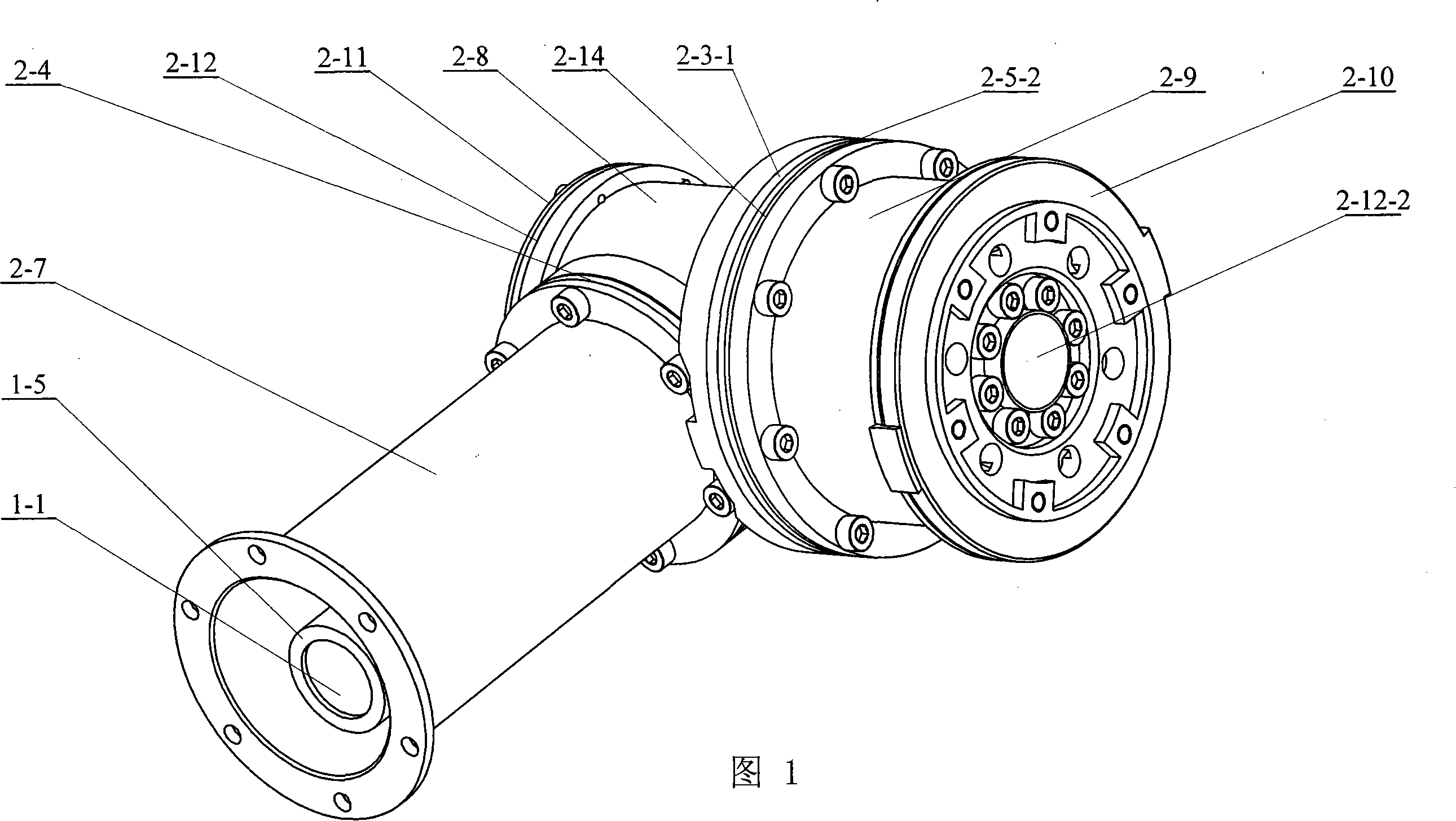
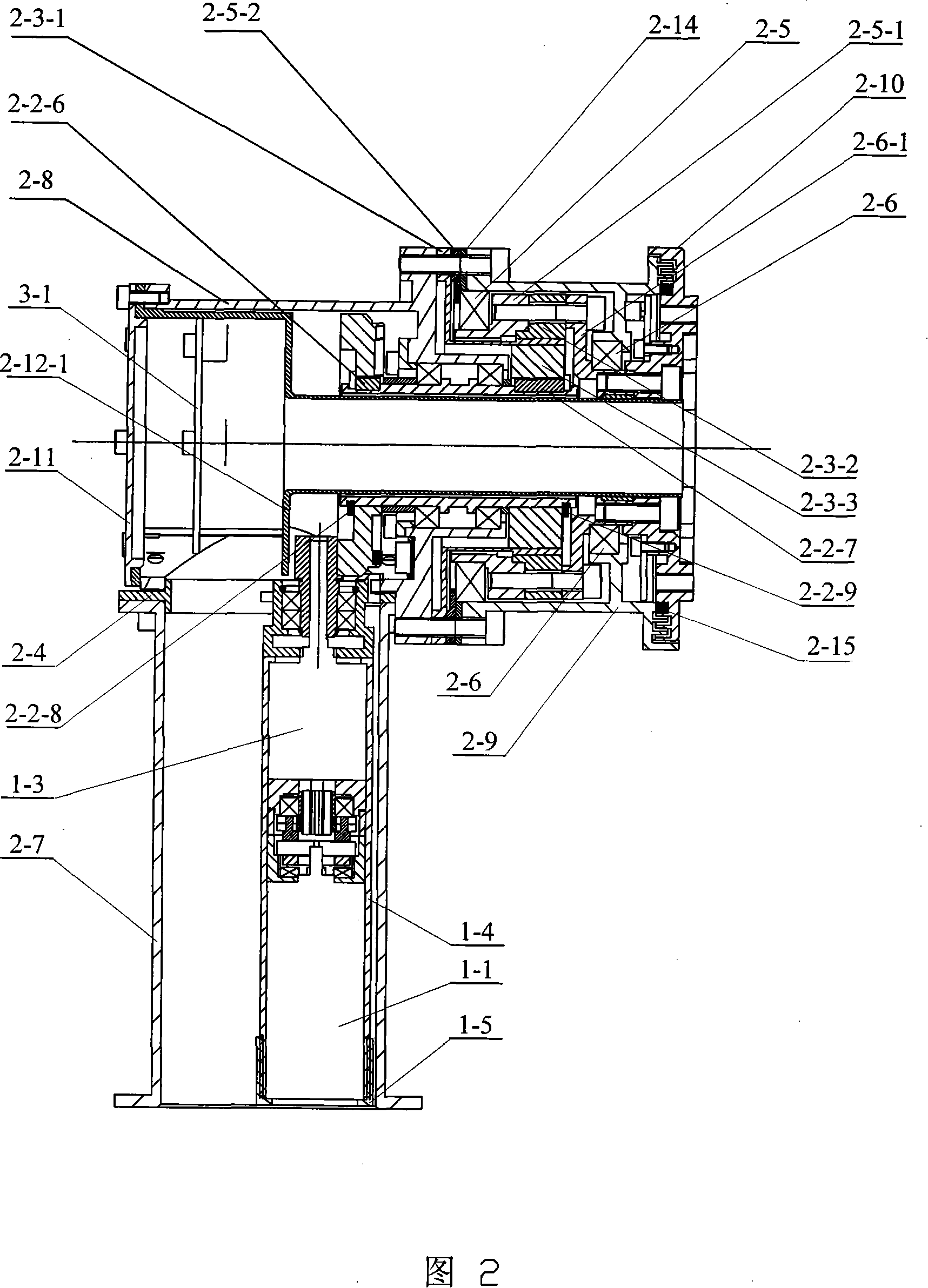
[0006]Specific Embodiment 1: (See Figures 1 to 11) This embodiment is composed of a drive device, a joint mechanism and an electrical part, and the drive device is composed of a DC brushless motor 1-1, a friction reverse brake, and a planetary reducer 1-3, motor sleeve 1-4 and motor sleeve cover 1-5, the joint mechanism is composed of eccentric motor sleeve fixing plate 2-4, crown gear device, hollow transmission shaft device, harmonic reducer , Thin-wall bearing one 2-5, thin-wall bearing two 2-6, thin-wall bearing one inner ring support seat 2-5-1, thin-wall bearing one outer ring retaining ring 2-5-2, thin-wall bearing two inner Ring support seat 2-6-1, first shell 2-7, second shell 2-8, third shell 2-9, output flange 2-10, joint rear end cover 2-11, sleeve 2- 12. Composed of an isolation support ring 2-13, an adjusting gasket 2-14 and a felt 2-15, the electrical part is composed of a Hall switch, a position sensor and an adapter circuit board 3-1, and the crown gear device...

specific Embodiment approach 2

[0008] Specific embodiment two: the motor sleeve 1-4 described in this embodiment, the motor sleeve cover 1-5, the hollow drive shaft 2-2-1, the sleeve one 2-2-3, the sleeve two 2-2 -4, hollow bearing cover 2-2-5, key one 2-2-6, key two 2-2-7, eccentric motor sleeve fixing plate 2-4, thin-walled bearing one inner ring support seat 2-5 -1. Thin-walled bearing first outer ring retaining ring 2-5-2, thin-walled bearing second inner ring support seat 2-6-1, first shell 2-7, second shell 2-8, third shell 2- 9. The output flange 2-10, the joint rear end cover 2-11 and the sleeve 2-12 are all made of titanium alloy material. Since the material of the bearing is 440C (stainless steel) and the difference in thermal expansion coefficient between titanium alloy (TC4) is very small, the bearing will not be stuck due to the large difference in thermal expansion coefficient between the inner ring seat of the bearing and the outer ring seat of the bearing and the inner and outer steel rings ...

specific Embodiment approach 3

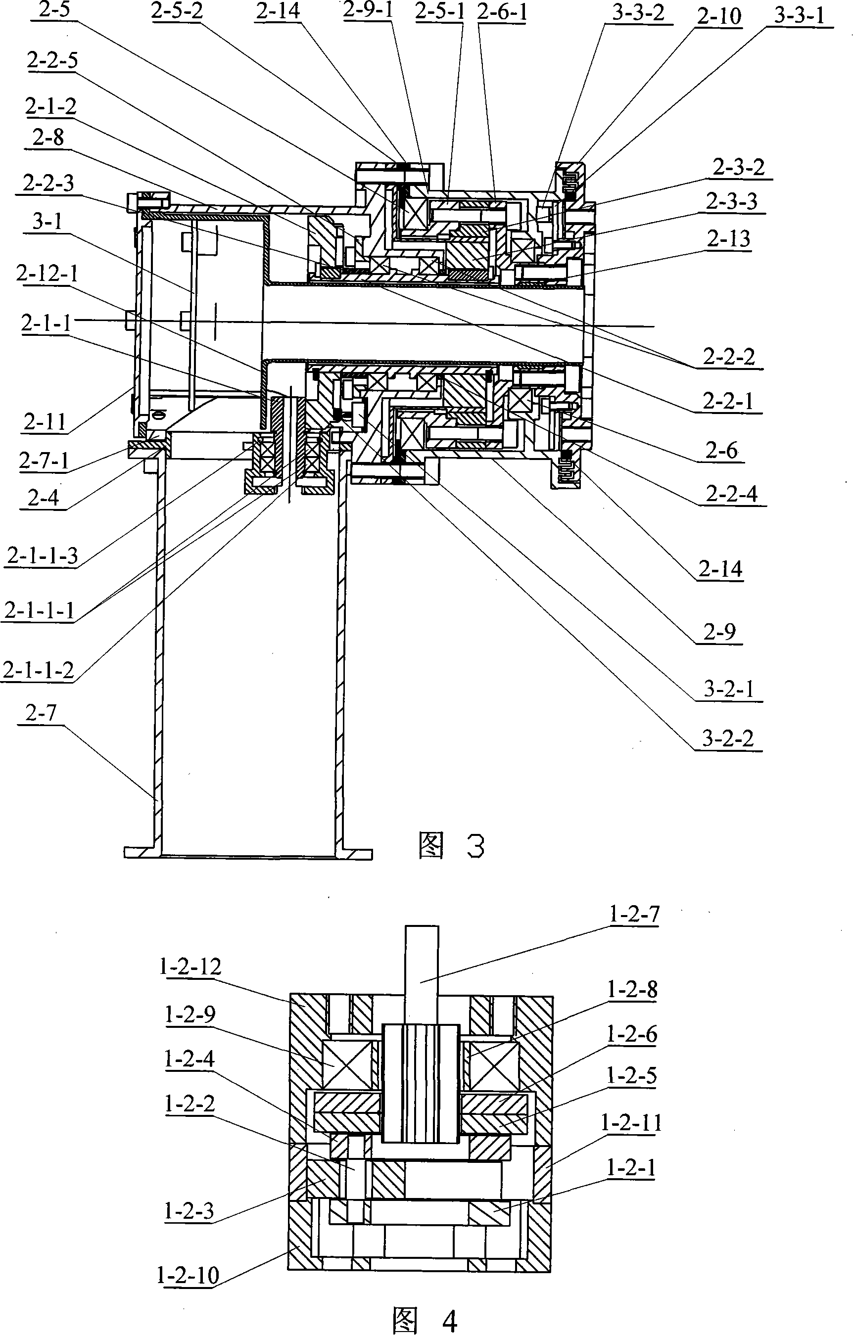
[0009] Specific embodiment three: In order to ensure reliable braking during reverse transmission in this embodiment, the friction plate 1-2-5, the friction plate 2 1-2-6 and the inner wall of the shell 3 1-2-12 The coefficient of friction is greater than , where r is the radius of the pitch circle of the output gear shaft 1-2-7, R is the inner diameter of the housing 3 1-2-12, and b is the width of the opening groove on the friction plate. The friction reverse brake consumes no power when braking. There is an appropriate interference fit between the cavity formed by the three bearings 1-2-3 and the output shaft of the motor, so that the three bearings 1-2-3 can squeeze the output of the brushless DC motor 1-1 axis. A clearance fit should be selected between the three pin shafts 1-2-2 and the inner rings of the three bearings 1-2-3. Other components and connections are the same as those in the first embodiment.


PUM


Abstract

The invention provides a vertical modular joint for space manipulator, relating to a modular joint for space manipulator. The invention aims to solve the problems with the prior space manipulator which is big in mass, size and power consumption but small in output torque of unit mass. A driving device of the invention is connected with a crown / Rolex gear series device, the crown / Rolex gear series device and a wave generator (2-3-3) is connected with a hollow transmission shaft (2-2-1), a rigid wheel (2-3-2) is connected with an inner ring support base (2-6-1) of a thin wall bearing two and the inner ring support base (2-6-1) of the thin wall bearing two is connected with an output flange (2-10). The invention has the advantages of high in integration and reliability, light in mass, small in size, low in power consumption, compact in structure, big in output torque of unit mass, high in position output precision and big in anti-bending rigidity, and is applicable to adapting to the environment of strong space radiation, high vacuum and big temperature difference, which has good maintainability and reliable operation performance.

Description

technical field [0001] The invention relates to a joint of a space manipulator. Background technique [0002] In the past ten or twenty years, my country's space technology has developed rapidly. In the future, our country will build its own space station in space, requiring space robots to carry out some tasks such as the construction and maintenance of space stations, the release, maintenance and recovery of satellites, etc. However, space robots are not yet able to complete these tasks. In the near future, our country will explore the moon, Mars and even other celestial bodies, and some operations in space are required, and these operations are inseparable from the space robotic arm. The modular joint is an important part of the space manipulator, and the performance of the modular joint determines the main performance of the whole manipulator. The space manipulator modular joint previously developed by DLR / HIT Joint Lab integrates drive and control into one joint. The ...

Claims


Application Information

Patent Timeline
Patent Type & Authority Applications(China)
IPC IPC(8): B25J17/00B25J13/00B25J19/00
Inventor 刘宏孙奎谢宗武李德伦黄剑斌
Owner HARBIN INST OF TECH
Why Eureka
Try Eureka