

Organic light emitting diode
A technology of light-emitting diodes and diodes, which is applied in the manufacturing of electrical components, electric solid-state devices, semiconductor/solid-state devices, etc., can solve the problems of increasing process steps and production costs, narrow band gap, etc. Production cost, the effect of simplifying the process flow
- Summary
- Abstract
- Description
- Claims
- Application Information
AI Technical Summary
Problems solved by technology
Method used
Image

Examples
Embodiment 1
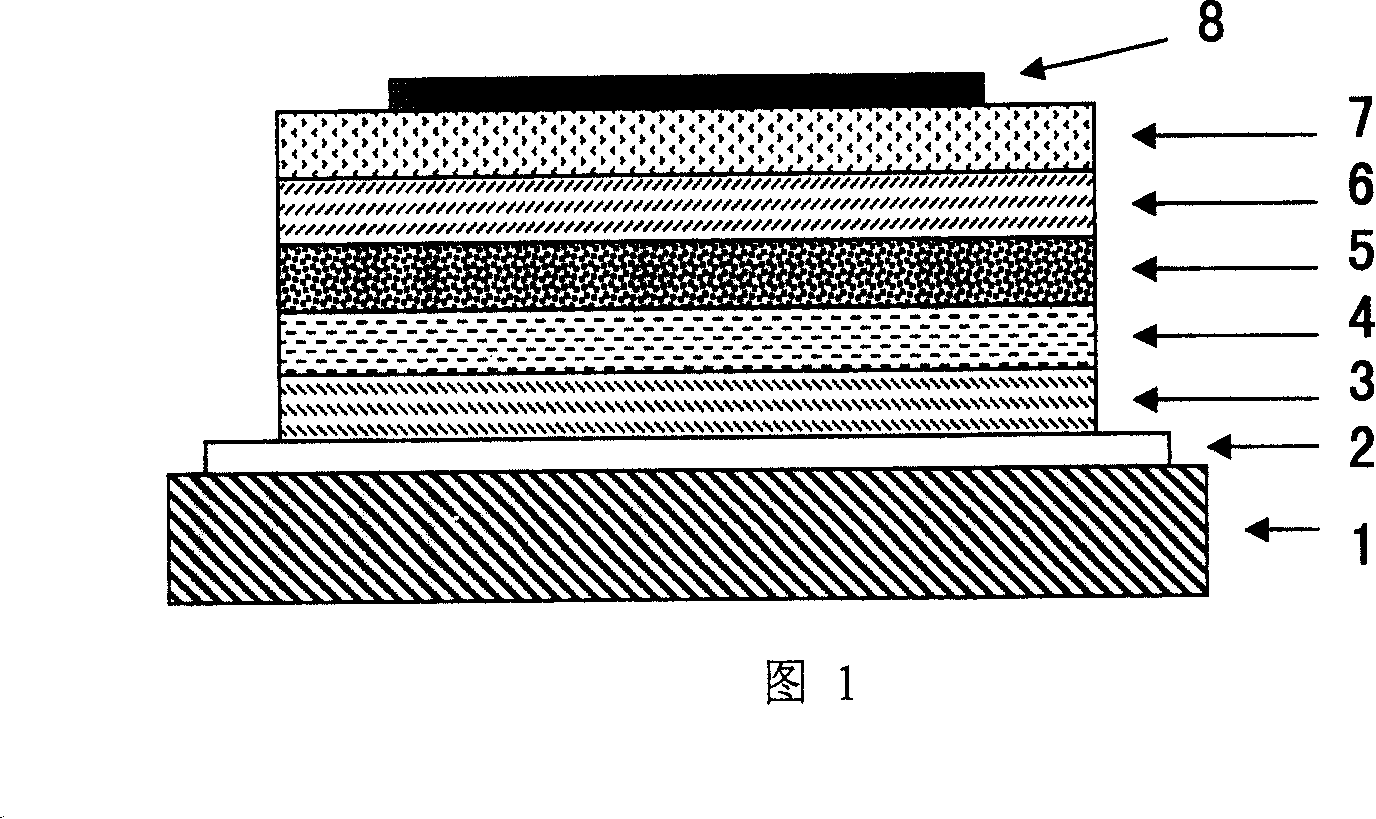
[0030] Please refer to the accompanying drawing 1, firstly, ITO is etched on the substrate 1 with ITO to form the anode 2, then the ITO is pretreated with oxygen plasma, and then copper phthalocyanine (CuPc), N, N is continuously evaporated on the ITO. -Diphenyl-N,N-di(2-naphthyl)-1,1-biphenyl-4,4-diamine (NPB), 9,10-(2-β-naphthyl)anthracene (ADN) : 3-(2-Benzothiazole)-7-diethylaminocoumarin (C6): 4-bicyclomethylene-2-tert-butyl-6-(1,1,7,7- Tetramethyljulonidine-4-vinyl)-4hydro-pyran (DCJTB), 8-hydroxyquinoline aluminum (Alq3), and lithium fluoride (LiF) were used as hole injection layer 3 and hole transport layer respectively. Layer 4, luminescent layer 5, electron transport layer 6, electron injection layer 7, and then vapor-deposit a layer of metal aluminum as the cathode 8, and finally package the device in anhydrous and oxygen-free manner to complete the device fabrication. Wherein the luminescent layer is co-evaporated from three sources, 3-(2-benzothiazole)-7-diethylam...
PUM
| Property | Measurement | Unit |
|---|---|---|
| Thickness | aaaaa | aaaaa |
Abstract
Description
Claims
Application Information