Hydrogen generation device, operation method thereof, and fuel cell system

A technology for generating devices and fuels, which is applied to fuel cells, fuel cell additives, fuel cell heat exchange, etc., and can solve the problems of ineffective hydrogen generation devices, poor economy, and reduced hydrogen generation efficiency, and achieves start-up time and Start-up characteristics, high reliability and economy, stable effect of modified reaction characteristics

Inactive Publication Date: 2008-02-06
PANASONIC CORP
View PDF1 Cites 4 Cited by
  • Summary
  • Abstract
  • Description
  • Claims
  • Application Information

AI Technical Summary

Problems solved by technology

The deviation of S / C from the set value not only affects the modification reaction characteristics relative to the modification catalytic temperature, but also causes uneven reaction of the gas after the modification reaction or the supply of raw materials once the S / C is too small. Occlusion of the flow path due to carbon precipitation due to high temperature, and further changes in the dew point of the generated gas sent from the hydrogen generator, which may affect the hydrogen generator gas device or the system using the hydrogen generator
[0006] In addition, if the hydrogen generator stops operating with liquid water accumulated, the water will freeze when the ambient temperature drops below 0°C, and there is a possibility that the hydrogen generator will not function due to damage to the water evaporator.
Furthermore, the stop in the state where the liquid water is accumulated may lead to the following situation, that is, even if the water is not frozen at the time of the stop, it will take an amount equivalent to the time until the water accumulated in the liquid water evaporates when the next start, due to the accumulation of liquid water. Water vapor supply occurs under unexpected conditions due to evaporation. In the unheated catalyst on the downstream side, water vapor condenses, which may lead to poor catalyst wetting or blockage of the water flow path.
In addition, if the water evaporator is always overheated and operated so as not to accumulate liquid water, the raw materials and fuel required for hydrogen production will increase, and the hydrogen generation efficiency will decrease, making it an economical hydrogen generator.

Method used


Image

  • Hydrogen generation device, operation method thereof, and fuel cell system
  • Hydrogen generation device, operation method thereof, and fuel cell system
  • Hydrogen generation device, operation method thereof, and fuel cell system

Examples


Embodiment approach 1

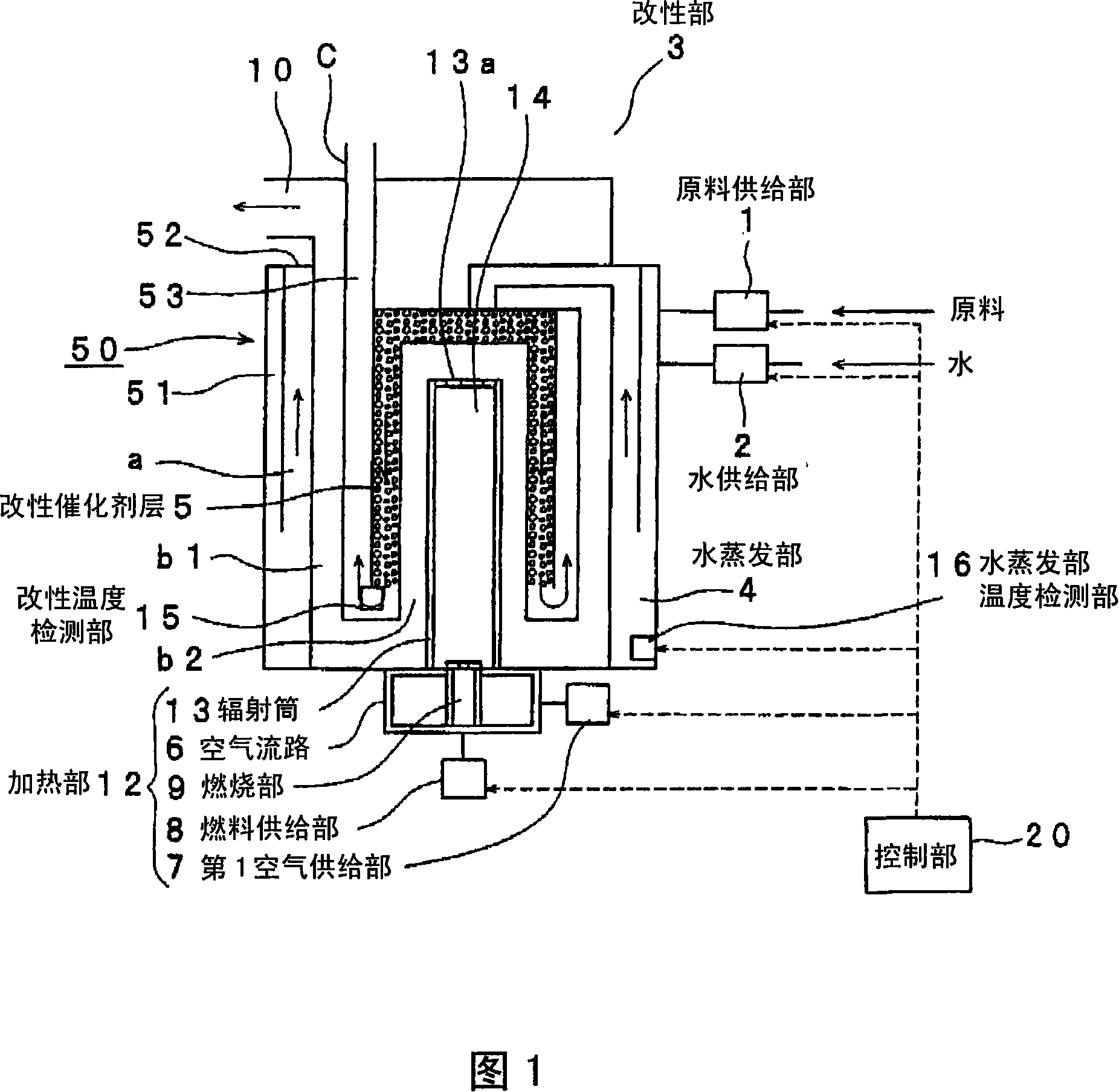
[0040] 1 is a schematic cross-sectional view showing the configuration of a hydrogen generator according to Embodiment 1 of the present invention, and particularly shows in detail the configuration of a reforming unit which is a main component of the hydrogen generator. As shown in FIG. 1 , the hydrogen generator is composed of a cylindrical body 50 with its upper end and lower end closed, and is equipped with a reforming device for steam reforming a raw material containing at least an organic compound composed of carbon and hydrogen to generate a hydrogen-containing gas. Section 3; water evaporation section 4 that supplies water vapor to the reforming section 3; temperature detection section 16 for the water evaporation section that detects the temperature of the water evaporation section 4 (hereinafter referred to as the temperature detection section); fuel and air are combusted, and The heating part 12 and the control part 20 are supplied to the heating part 12 and the contr...

Embodiment approach 2

[0062] The hydrogen generator related to this embodiment has the same function as that of Embodiment 1 except that the control unit has a function of judging whether or not water has started to accumulate in the water evaporator based on a threshold value composed of a time-varying value of the detected temperature instead of the critical temperature. constitute.

[0063] For example, when the detection temperature of the water evaporator 4 is 130°C, when the time change value ΔTw of the detection temperature is -1.0 deg / min, liquid water will not accumulate even after 10 minutes, but the ΔTw is -2.0 deg / min It only takes 5 minutes for water to start accumulating. In addition, when the detection temperature is 120°C, when the time change value of the detection temperature ΔTw is -0.5deg / min, liquid water will not accumulate even after 10 minutes, but it only takes 5 minutes when the ΔTw is -1.0deg / min It started to accumulate water.

[0064] Therefore, in the operating metho...

Embodiment approach 3

[0070] In the hydrogen generator related to this embodiment, when the control unit judges that the water evaporator has started to accumulate water, the amount of liquid water is not increased by evaporating the liquid water. It has the same structure as Embodiment 1 except for the function of controlling the amount of fuel in the fuel tank.

[0071] It is assumed that a normal operation is performed with a predetermined amount of fuel, for example, 1.5 NLM. When the detected temperature of the water evaporator 4 is below the critical temperature, for example, 110° C., the control unit 20 increases the amount of fuel supplied from the fuel supply unit 8 . When city gas 13A is supplied as fuel, the predetermined value 1.5NLM is increased by 0.2NLM to become 1.7NLM. On the other hand, when the detected temperature is 110° C. or higher, the fuel amount is returned to the predetermined flow rate of 1.5 NLM.

[0072] FIG. 7 is a graph showing the temperature of the water evaporat...


PUM


Abstract

A hydrogen generation device includes: a reforming unit for steam-reforming raw material containing at least carbon atoms and hydrogen atoms to generate a hydrogen-containing gas; a raw material supply unit for supplying a raw material to the reforming unit; a steam generation unit for supplying steam to the reforming unit; a steam generation unit temperature detection unit for detecting the temperature of the steam generation unit; a heating unit for supplying a combustion gas for successively heating the reforming unit and the steam generation unit by heat transfer; and a control unit. The control unit controls a raw material supply amount from the raw material supply unit and a water supply amount from a water supply unit and controls one of the air amount to the heating unit, a fuel amount to the heating unit, and the raw material amount to the reforming unit so that no water remains in the steam generation unit according to the detected temperature from the steam generation unit temperature detection unit. Thus, it is possible to operate the hydrogen generation device without leaving water in the steam generation unit and to provide a hydrogen generation device operation method having a high reliability and economy and a hydrogen generation device using the same as well as a fuel cell generation system using the hydrogen generation device.

Description

technical field [0001] The present invention relates to a hydrogen generation device and its operating method and fuel cell system, which use natural gas, LPG, gasoline, naphtha, kerosene, methanol and other hydrocarbon-based substances as main raw materials, and use water vapor modification reaction to generate hydrogen-enriched gas. The invention relates to a hydrogen generating device for generating hydrogen supplied to hydrogen utilization equipment such as a fuel cell, an operating method thereof, and a fuel cell system. Background technique [0002] The hydrogen generator performs steam reforming of a raw material containing at least an organic compound composed of carbon and hydrogen in a reforming section provided with a reforming catalyst layer. Through this modification reaction, a hydrogen-enriched gas (hereinafter referred to as hydrogen gas) is generated as a modified gas. If water is directly supplied to the reforming catalyst layer during the reforming reacti...

Claims


Application Information

Patent Timeline
Patent Type & Authority Applications(China)
IPC IPC(8): C01B3/38H01M8/04H01M8/06
CPCH01M8/0618C01B2203/0822H01M8/04798H01M8/04373H01M8/04089C01B3/384C01B2203/169Y02E60/50C01B2203/0827C01B2203/1695H01M8/04835C01B2203/066H01M8/04708H01M8/04738C01B2203/0811C01B2203/0233H01M8/04007H01M8/0631Y02P20/10
Inventor 前西晃麻生智伦向井裕二
Owner PANASONIC CORP
Why Eureka
Try Eureka