Manufacturing method for round knitting machine needle cylinder surface optimization

A circular knitting machine and a manufacturing method technology, which are applied in the direction of knitting, weft knitting, and circular knitting machines for weft knitting with individual moving needles, etc., which can solve the problems of reducing the service life of the machine tool, the machine cannot operate, and fine debris remains

Inactive Publication Date: 2008-02-20
蔡志欣 +1
View PDF0 Cites 4 Cited by
  • Summary
  • Abstract
  • Description
  • Claims
  • Application Information

AI Technical Summary

Problems solved by technology

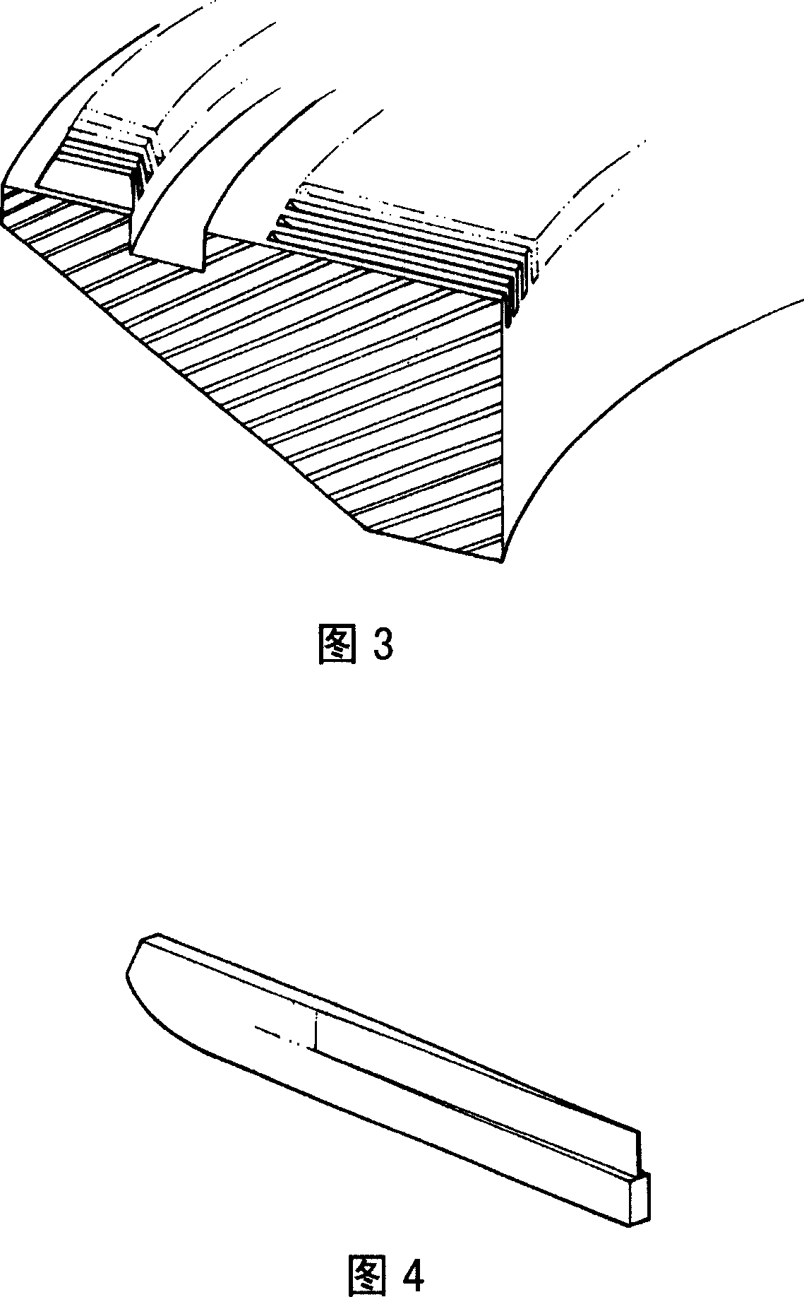
[0004] However, in the above-mentioned process, those guide grooves on the needle cylinder after milling and grinding usually inevitably have residual burrs or rough and uneven surfaces (as shown in Figure 7), and if these defects are not removed , in the future knitting operation, it will cause tight needles and jammed needles in the active components such as raw gram pieces. This kind of component interference phenomenon will not only cause vertical stripes in the knitted fabric, but also cause bifurcation of hooked yarns. , breakage or fluffing and other defects will seriously reduce the product quality, and will also cause high wear and tear of related components, which will reduce the service life of the machine tool, and even cause component damage and machine failure.
[0005] In order to avoid the above defects caused by cutting burrs and surface roughness, the industry usually depolishes the guide groove of the syringe in the last process, and uses polishing wheels, fine grinding wheels or jet grinding to remove burrs. And improve the surface smoothness of the knitting needle guide groove; however, according to past practical experience, when using a polishing wheel made of steel wire, copper wire or emery cloth for polishing, not only the grinding time is long, but also the open and flat surface of the workpiece can only be ground The surface part cannot go deep into the inner surface of narrow gaps such as guide grooves (as shown in Figure 8); while using a fine grinding wheel for polishing, although it has good grinding correction and leveling effects for workpieces made of harder materials, the grinding wheel The fine abrasive grains on the surface are easy to fall off during grinding or the grinding debris is easy to cause the grinding wheel to be filled, so that it is difficult to achieve a high-quality mirror polishing grinding effect. In addition, the use of fine grinding wheels is also the same as the use of polishing wheels. long, unable to penetrate into the inner surface of the guide ditch; as for the jet grinding cleaning method, very fine sand is used as the detergent medium, although the inner surface of the narrow pores such as the guide ditch can be cleaned by jet grinding, but there are fine particles For residual problems, it often takes a lot of time and manpower to clean up and check to confirm that there are no residual fine sand particles after processing, because if the residual fine particles are not cleaned, the above-mentioned defects will also be derived.
In addition, the above-mentioned various mechanical polishing methods often have a large gap in polishing results due to different personal operating skills; in addition, because the grinding and cutting process of polishing will affect the formation of work-hardened layer and the change of lattice structure on the surface, Therefore, the corrosion resistance and wear resistance are weakened, it is easy to oxidize again, and the luster is not durable, and the high heat generated during the polishing and grinding process will also cause stress deformation of the workpiece, especially the thin spacers on both sides of the guide groove are more difficult to avoid

Method used


Image

  • Manufacturing method for round knitting machine needle cylinder surface optimization
  • Manufacturing method for round knitting machine needle cylinder surface optimization
  • Manufacturing method for round knitting machine needle cylinder surface optimization

Examples


Embodiment Construction

[0032] Other objects and innovative features of the present invention will be further clarified by referring to the following description.

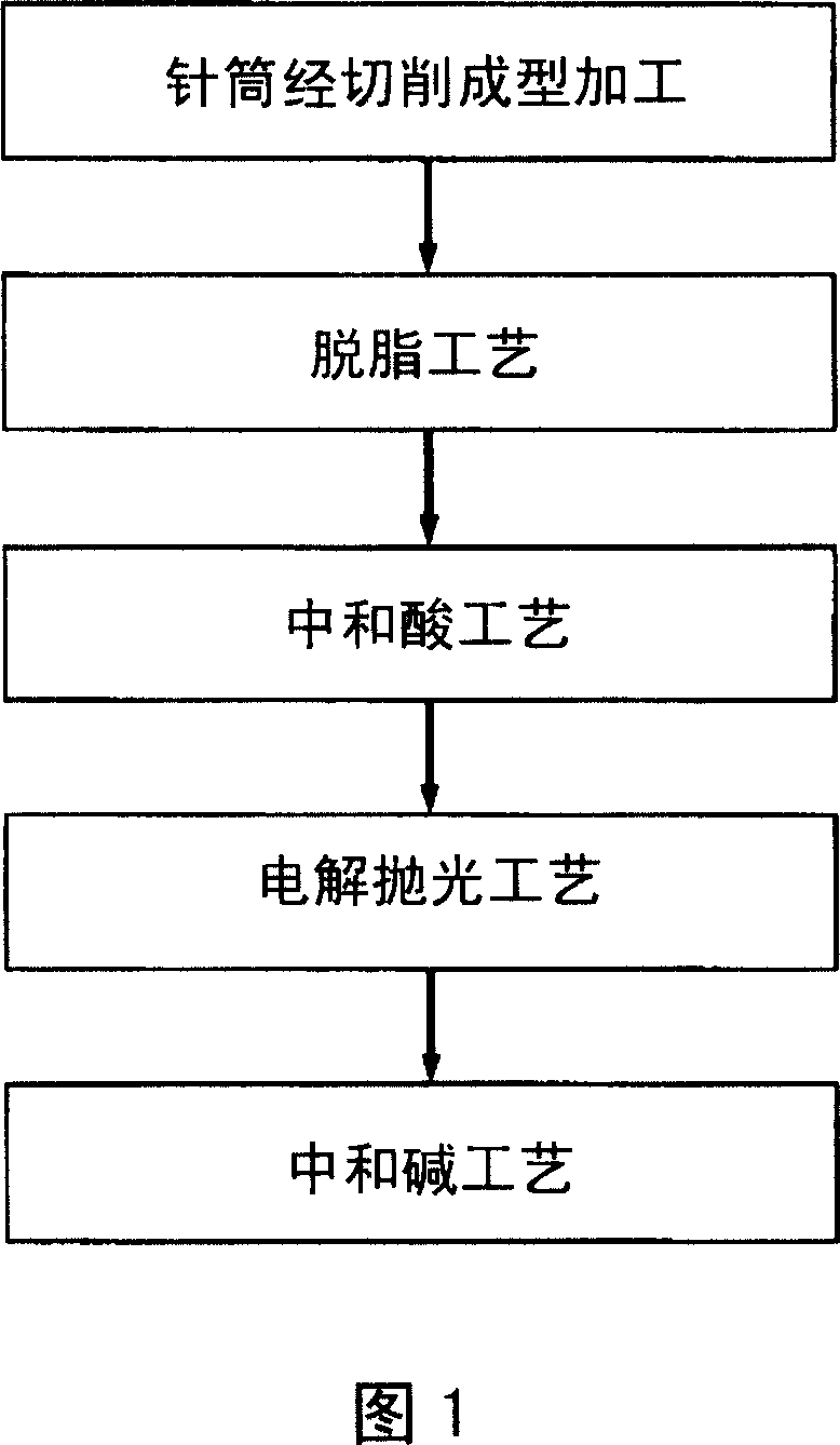
[0033] As shown in Fig. 1, the manufacturing method of circular knitting machine needle cylinder surface optimization of the present invention is roughly: select the needle cylinder workpiece through the guide groove cutting process once, and the surface of the needle cylinder is processed through preliminary surface grinding to make the surface of the workpiece rough. The thickness is less than 100μm, and then the syringe workpiece is sequentially subjected to degreasing process→neutralizing acid process→electrolytic polishing process→neutralizing alkali process, thereby improving the smoothness, gloss, corrosion resistance, Anti-adhesion and aesthetics, and achieve the purpose of simplifying processing technology and improving processing efficiency.

[0034] Among them, the operation of the degreasing process is to first apply a degreas...


PUM

PropertyMeasurementUnit
thicknessaaaaaaaaaa

Abstract

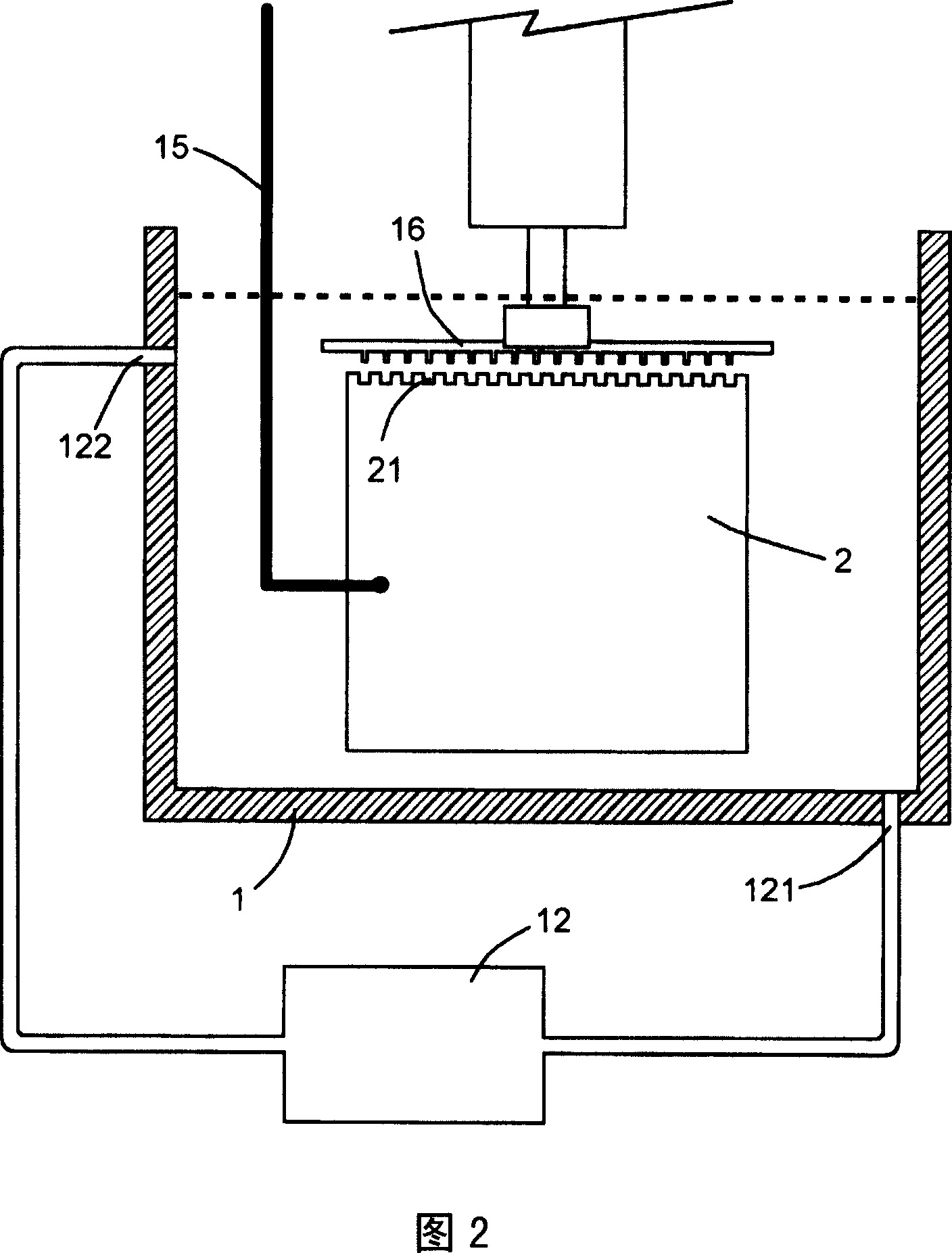
The invention discloses a manufacturing method of optimizing the surface of a round needle weaving machine syringe. The manufacturing method comprises the following steps: providing a syringe work piece finished with cutting and shaping as well as processing operations; operating degreasing technique on the syringe work piece; operating electrolytic polishing technique and immersing the syringe work piece into the electrolytic polishing groove fed with electrolytic liquids so as to make the syringe electrically connected with the anode of a power supply; in addition, arranging a correspondingly shaped cathode nearby the part to be polished of the syringe, and selecting suitable operating parameters on voltage and electric current as well as electrolytic time so as to make the surface of the syringe work piece happed anode electrolytic reaction. In this way, the invention improves the smoothness, glossiness and anti adhesiveness as well as beauty of the surface of the slot for the syringe, and further simplifies the processing technique as well as achieves the improvement of the processing efficiency.

Description

field of invention [0001] The invention relates to a manufacturing method for optimizing the surface of a circular knitting machine needle cylinder, in particular to a needle cylinder manufacturing method capable of improving the flatness and smoothness of the guide groove surface on the needle cylinder. Background technique [0002] Press, the circular knitting machine mainly uses the SINKER / knitting needle to reciprocate on the needle cylinder to interweave the cotton thread and weave it into cloth, so there are many small guide grooves on the needle cylinder to guide the The reciprocating motion of the raw gram / knitting needle, and because the guide groove and the raw gram / knitting needle are in a state of high-speed relative motion during the weaving operation, the setting of the guide groove on the needle cylinder must have precise dimensions And a smooth surface, so as to avoid severe abrasion caused by high-speed operation between parts, resulting in many unfavorable ...

Claims


Application Information

Patent Timeline
Patent Type & Authority Applications(China)
IPC IPC(8): C25D11/02D04B9/06D04B15/14
Inventor 蔡志欣侯谷青
Owner 蔡志欣
Why Eureka
Try Eureka