Draining pump of air-conditioning plant

A drainage pump and pump body technology, which is applied to pump devices, components of pumping devices for elastic fluids, pumps, etc., can solve the problems of reduced blade efficiency and low workmanship efficiency, and achieve improved drainage efficiency, elimination of disturbance, and The effect of expanding the inner wall area

Inactive Publication Date: 2008-02-20
SHANGHAI JUNLE REFRIGERATION CONTROL
View PDF2 Cites 4 Cited by
  • Summary
  • Abstract
  • Description
  • Claims
  • Application Information

AI Technical Summary

Problems solved by technology

The drainage pump with this structure adopts the impeller in the form of straight blades, so the work efficiency is relatively low, and the setting of the rectifying ring around the blades greatly reduces the efficiency of the blades to drain outward.

Method used


Image

  • Draining pump of air-conditioning plant
  • Draining pump of air-conditioning plant

Examples


Embodiment Construction

[0025] In order to make the technical means, creative features, goals and effects achieved by the present invention easy to understand, the present invention will be further described below in conjunction with specific embodiments.

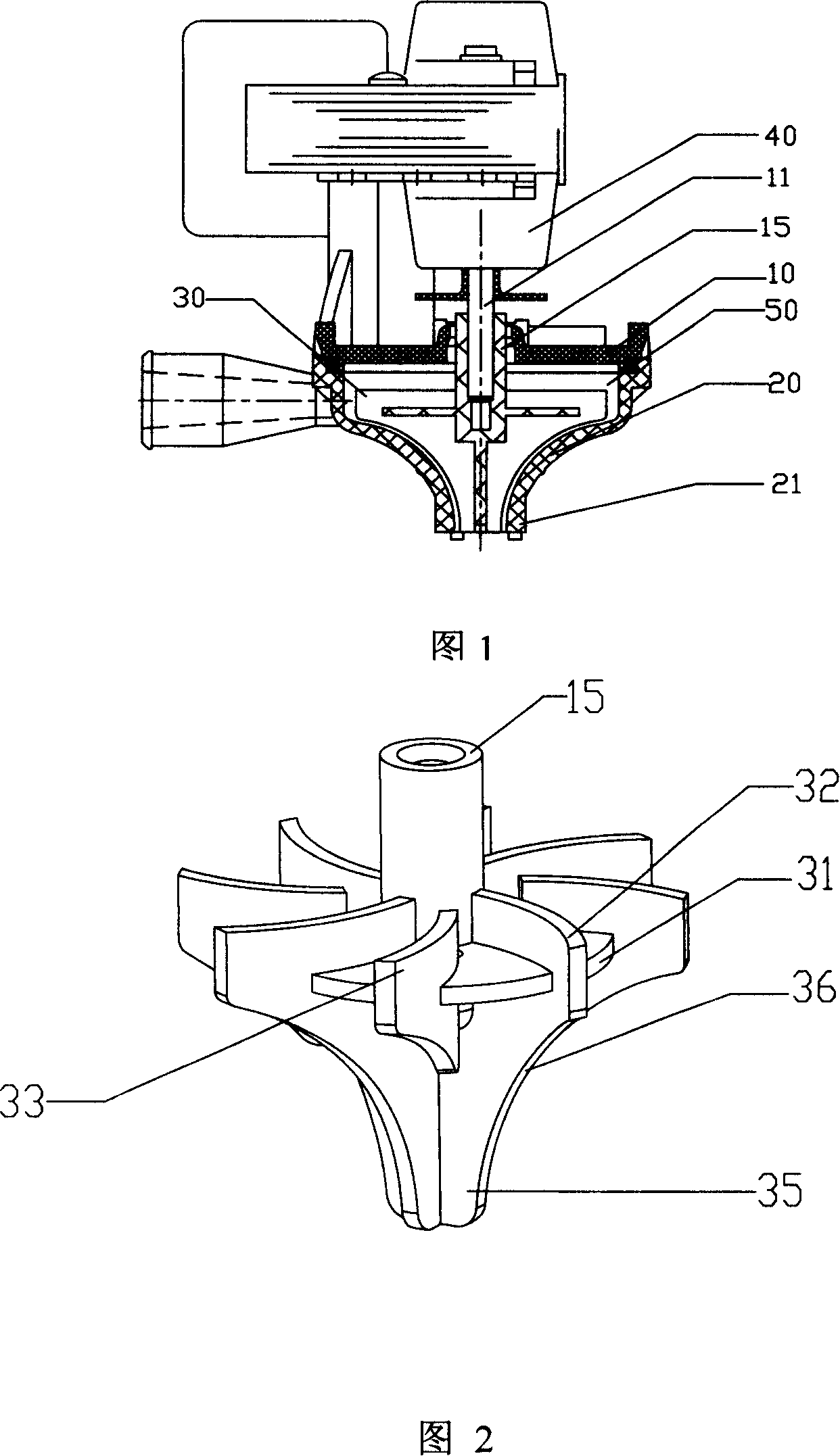
[0026] Fig. 1 is a structural schematic diagram of the present invention. The drainage pump of the present invention includes an upper pump body 10, a lower pump body 20, an impeller 30 installed in the chamber 50 formed by the upper pump body 10 and the lower pump body 20, and a motor 40 that drives the impeller 30 to rotate. 11 is the motor 40 The output shaft, the output shaft 11 is sleeved in the shaft sleeve 15 of the impeller 30 . The bottom of the impeller 30 stretches into the water inlet 21 of the lower pump body.

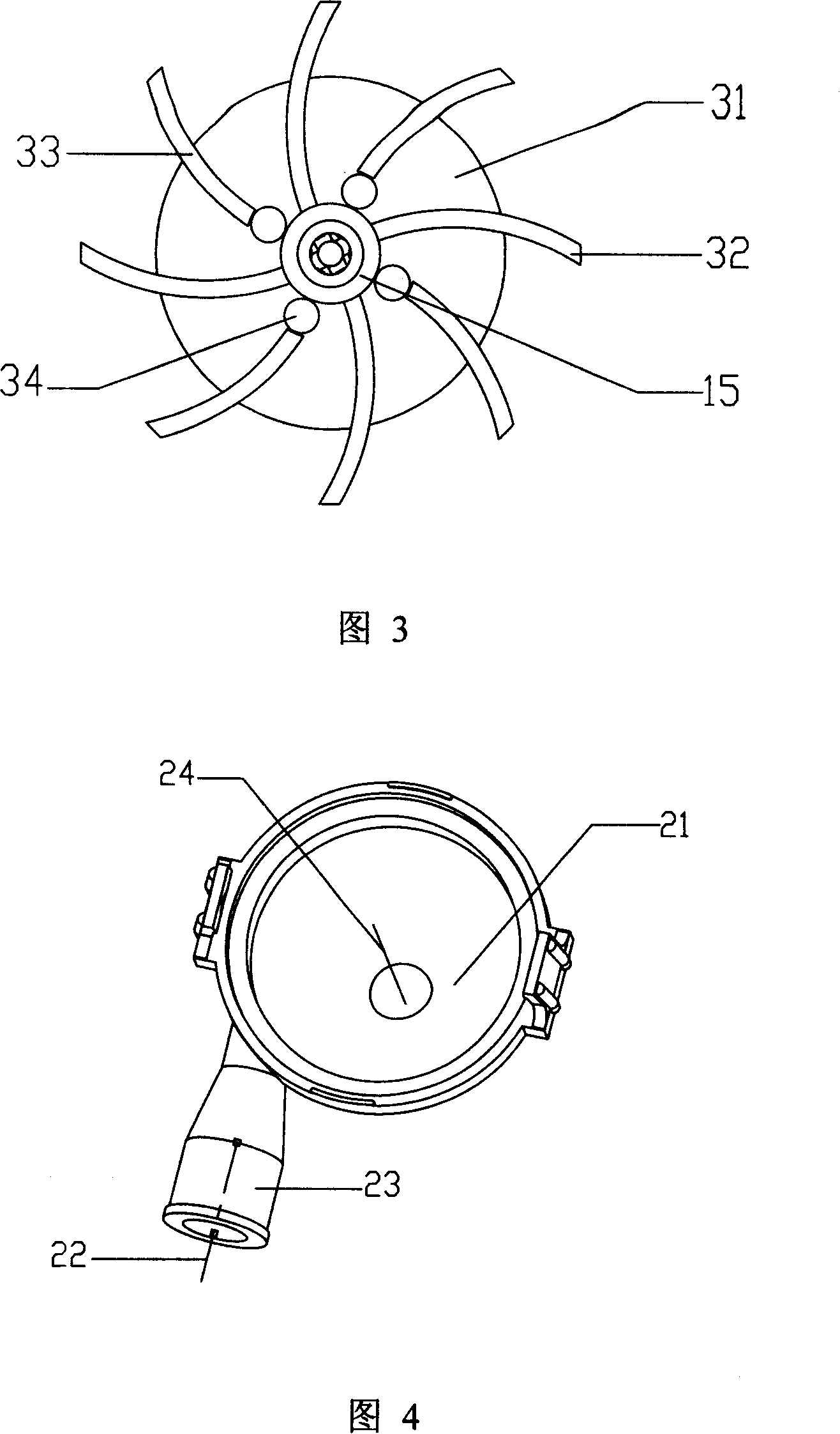
[0027] Fig. 2 is a three-dimensional structure diagram of the impeller. At the bottom of the axle sleeve 15, there is a disc 31 centered on the axle sleeve. The arrangement of the disc 31 strengthens and strengthens the ant...


PUM


Abstract

The invention relates to a draining pump, the upper part of the impeller of the draining pump is provided with a shaft sleeve which is connected with a motor drive shaft, a big camber blade connected with the shaft sleeve and a small camber blade that is not connected with the shaft sleeve; the radian of the two kinds of blades is the same, a round disc which has the functions of the connecting and strengthening is arranged in the middle of the two kinds of camber blades, the diameter of the round disc is less than the outer edge of the blade; the big camber blade and the small camber blade are all vertical to the round discs. The large camber blade and the small camber blade all bend and extend outward from the disc with a direction contrary to the rotation direction of the electric motor. The big blade extends downward along the shaft sleeve and forms the small diversion blades which are vertically to each other, the bottom is at the water inlet of the pump body, the radian of the small diversion blades equals to that of the big camber blade, but the width is less than that of the big camber blade, the diversion blades are connected with the big camber blade through a transition curved surface and forms an integrated body. The invention adopts the integrated structure of the diversion blade and the big camber blade, which considerably improves the draining efficiency of the draining pump, eliminates the disturbance to the water flow from the boundary surface and reduces the noise.

Description

technical field [0001] The invention relates to a drain pump installed on an air conditioner to remove condensed water. Background technique [0002] When the air conditioner is running, a large amount of condensed water will be generated on the surface of the heat exchanger due to the cooling of the air. When the water accumulates to a certain extent, it will drip into the condensed water tank below the heat exchanger. The pump removes the condensate to the outside. This type of drainage pump requires a certain flow rate and head, and due to the strict requirements of the use environment on the noise of the air conditioning system, the working noise of the drainage pump must be limited within a certain range. [0003] Chinese patent ZL95107436.9 once disclosed a technical scheme of a drainage pump. The drainage pump is composed of a pump body with a suction port at the lower end and a discharge port at the upper side. The motor for rotating the rotating body is composed o...

Claims


Application Information

Patent Timeline
Patent Type & Authority Applications(China)
IPC IPC(8): F04D13/06F04D29/24F04D29/42F24F13/22
Inventor 张元强刘小蓉陈文勇
Owner SHANGHAI JUNLE REFRIGERATION CONTROL
Why Eureka
Try Eureka