
Centrifugal atomizing plasma spraying machine and its spray coating technique

A centrifugal atomization, plasma technology, applied in metal material coating process, ion implantation plating, coating and other directions, to achieve the effect of good sphericity, uniform coating performance, and ensure uniformity

Inactive Publication Date: 2008-02-27
ACADEMY OF ARMORED FORCES ENG PLA
View PDF2 Cites 3 Cited by
  • Summary
  • Abstract
  • Description
  • Claims
  • Application Information

AI Technical Summary

Problems solved by technology

[0004] The purpose of the present invention is to solve the following key technical problems in view of the shortcomings of traditional thermal spraying technology when spraying the inner holes of parts:

Method used


Image

  • Centrifugal atomizing plasma spraying machine and its spray coating technique
  • Centrifugal atomizing plasma spraying machine and its spray coating technique
  • Centrifugal atomizing plasma spraying machine and its spray coating technique

Examples


Embodiment Construction

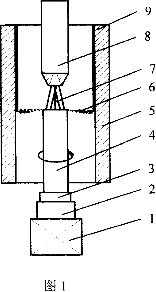
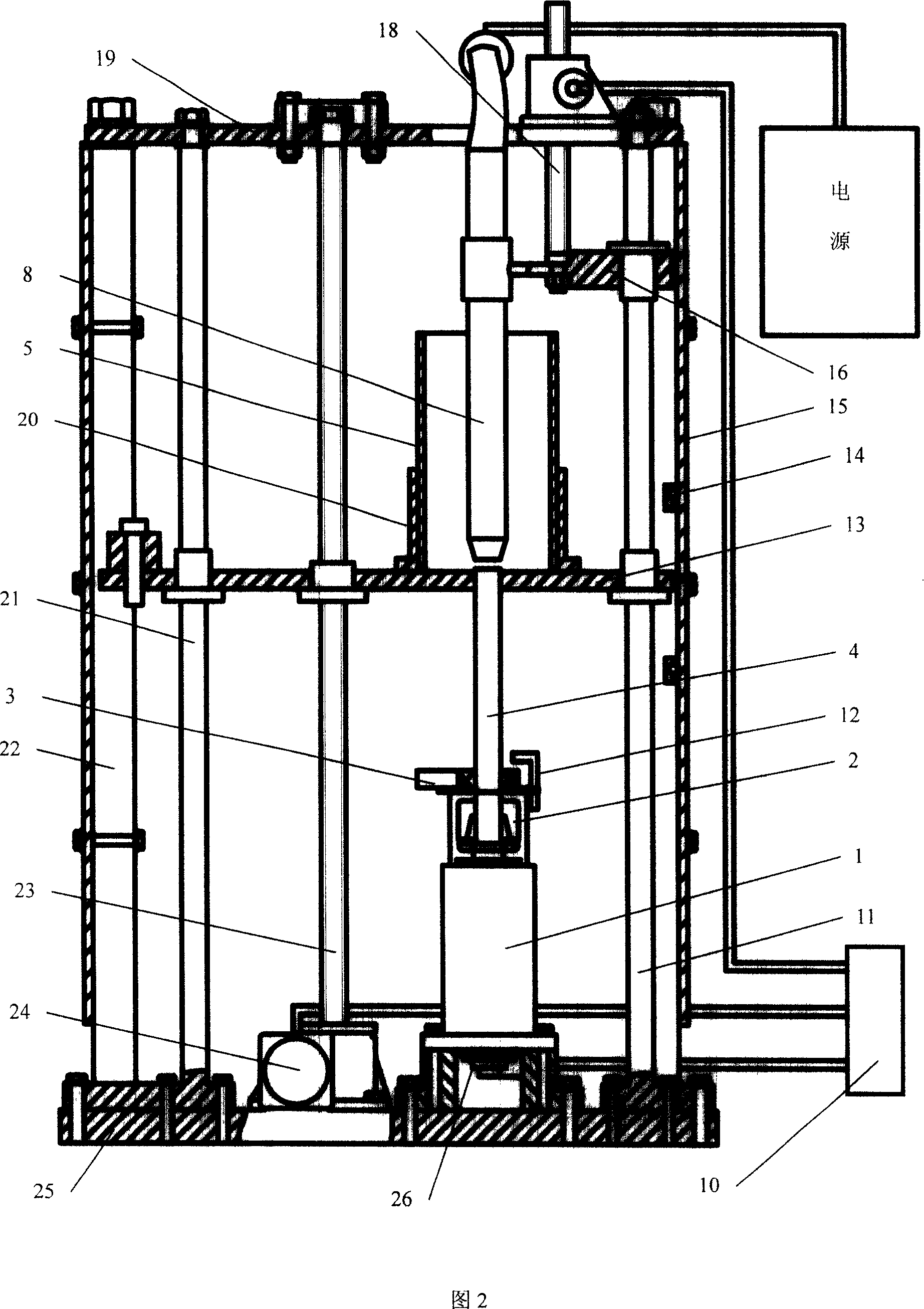
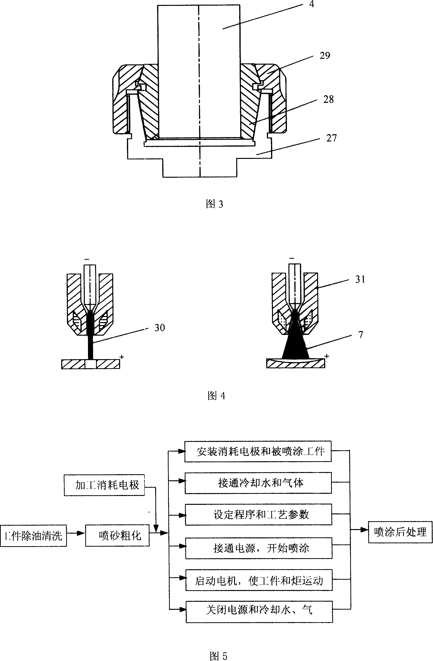
[0040] Fig. 1 is a schematic diagram of the working principle of the plasma spraying machine of the present invention. The sprayed material is processed into a cylindrical rod with a length of 100-400mm and a diameter of Φ15-40mm, which is used as a consumable electrode 4, and the consumable electrode 4 passes through the consumable electrode holder 2 It is connected with a high-speed motor 1 with a rotating speed of 15000-25000r / min and a power of 2.2kw. An ordinary high-speed bearing 3 is installed on the consumable electrode and connected with the anode of the power supply. When the consumable electrode rotates at high speed and the plasma torch 8 generates a transfer-type conical plasma arc 7, the plasma arc continuously melts the end of the consumable electrode, and the molten material is atomized and accelerated under the centrifugal force generated by the high-speed rotation , to form spray particles 6 , and the spray particles are sputtered onto the surface of the workp...


PUM

PropertyMeasurementUnit
particle sizeaaaaaaaaaa

Abstract

The present invention discloses a plasma spraying machine based on centrifugal atomization principle and thermal spraying process by utilizing said spraying machine. Said plasma spraying machine is formed from centrifugal atomization mechanism, plasma cutting torch, feeding mechanism, control system, cooling system, machine frame and protective device. Said invention can be used for thermal-spraying surface of internal hole whose minimum hole diameter is 70mm.

Description

1. Technical field [0001] The invention belongs to the technical field of metal surface treatment and thermal spraying, and relates to a novel thermal spraying technology for depositing a coating on the surface of an inner hole of a component, and is particularly suitable for spraying a coating on the surface of a small-diameter inner hole. 2. Background technology [0002] Wear and corrosion are important reasons that affect the service life and reliability of parts. Using thermal spraying technology to deposit wear-resistant or anti-corrosion coatings on the surface of parts is one of the effective technical means to solve the wear or corrosion of parts. However, for the inner holes of parts with smaller diameters, it is difficult for various traditional thermal spraying techniques to spray effective coatings on the inner surface due to the limitation of the spraying space. This is because: 1) the traditional thermal spraying technology spray gun The size is large, and it ...

Claims


Application Information

Patent Timeline
Patent Type & Authority Applications(China)
IPC IPC(8): C23C4/06C23C14/34
Inventor 朱有利李占明叶雄林杜晓坤黄元林
Owner ACADEMY OF ARMORED FORCES ENG PLA
Learn More