Prepositive differential amplifier and method for expanding its input range

A pre-differential, input range technology, applied in differential amplifiers, DC-coupled DC amplifiers, analog-to-digital converters, etc. The effect of dynamic range

Active Publication Date: 2008-02-27
RIGOL
View PDF0 Cites 22 Cited by
  • Summary
  • Abstract
  • Description
  • Claims
  • Application Information

AI Technical Summary

Problems solved by technology

[0004] (1) Since the AD chip with differential input is usually powered by a single power supply, the midpoint potential of the differential input needs to be raised by 1 / 2 of the voltage input range to effectively use the input dynamic range. For example, when connecting with a single-ended signal, it needs to be The single-ended signal must be raised to connect, and the dynamic range of the input will be lost
[0005] (2) If the unbalanced input method is used, although high input impedance can be obtained, in this method, one input of the amplifier is used as a ground reference, and the two input op amps cannot share the amplification of the differential mode signal, so it is effective The input range is more than 1 / 2 smaller than that of the balanced input mode. At the same time, the amplifier and follower of the unbalanced input mode have no suppression effect on the AC common mode interference due to the single-ended input mode, and completely rely on analog and digital filtering to eliminate it. Therefore, the common mode rejection performance is also degraded.
[0006] (3) If the balanced input method is used, there is usually no common terminal between the signal under test and the amplifier. To make the buffer with high input impedance work normally, it must provide a path for its input bias current, otherwise the two input terminals are suspended, due to the input The accumulation of charge on the capacitor will eventually cause the input op amp to exceed the common mode range and enter the saturation state
These not only make the circuit very complicated, the cost is greatly increased, but also the speed performance of the amplifier is reduced.

Method used


Image

  • Prepositive differential amplifier and method for expanding its input range
  • Prepositive differential amplifier and method for expanding its input range

Examples


Embodiment 1

[0028] The invention provides a method for extending the input range of the pre-differential amplifier. In the method, the pre-differential amplifier can be set in a balanced input mode and an unbalanced input mode by switching. It provides a wide input range and high impedance amplifier solution for the front-end amplifier design of electronic measuring instruments. For this purpose, the output of one end of the high-impedance buffer of the differential input is reversed and then fed forward to the other end (one end can be positive or negative), or the output of the differential-mode voltage of the high-impedance buffer - 1 / 2 feed forward to the inverting input. At the same time, a DC bias voltage can also be added during reverse amplification to raise the midpoint potential of the balanced input to achieve potential shifting.

Embodiment 2

[0030] The invention provides a pre-differential amplifier, which can be set to a balanced input mode and an unbalanced input mode by switching the differential amplifier. It provides a wide input range and high impedance amplifier solution for the front-end amplifier design of electronic measuring instruments. For this purpose, the output of one end of the high-impedance buffer of the differential input is reversed and then fed forward to the other end (one end can be positive or negative), or the output of the differential-mode voltage of the high-impedance buffer - 1 / 2 feed forward to the inverting input. At the same time, a DC bias voltage can also be added during reverse amplification to raise the midpoint potential of the balanced input to achieve potential shifting.

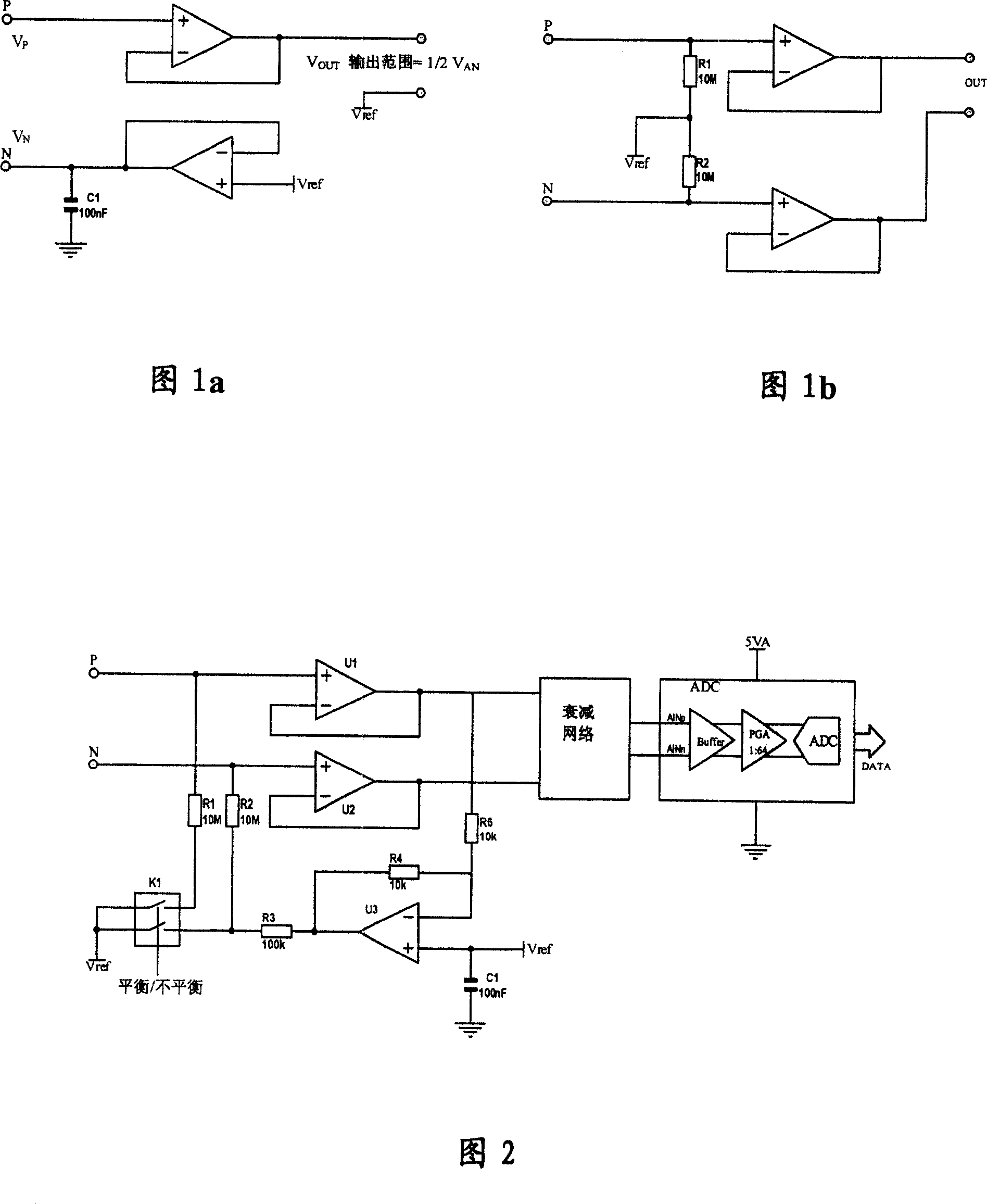
[0031] As shown in Figure 2, it is the circuit form of Embodiment 1 of the present invention: U1 and U2 are input buffer amplifiers, which adopt CMOS or JFET structure high-voltage zero-drift operational ...

Embodiment 3

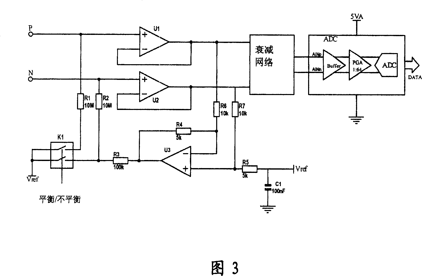
[0034] As shown in Figure 3, it is the circuit form of Embodiment 3 of the present invention: U1 and U2 are input buffer amplifiers, which adopt CMOS or JFET structure high-voltage zero-drift operational amplifiers. In the circuit of Figure 3, the input buffer gain is 1. The connection form of the output feedforward amplifier U3 is shown in Figure 3. In Fig. 3, the differential mode signal output by the buffer is attenuated by G=-1 / 2 and fed back to the input terminal of U2. In the case of normal operation, the feedback amount of the two connection methods shown in Figure 2 and Figure 3 is the same, and the DC operating point is also the same, but the suppression performance of common mode noise is different. At the same time, U3 assumes the role of voltage translation, raising the midpoint potential (VP+VN) / 2 of VP and VN to VREF.

[0035] The signal after the buffer is connected to an attenuation network to ensure that the large signal does not exceed the voltage input rang...


PUM


Abstract

This invention relates to a method for extending the range of the input of a pre-differential amplifier. It is composed of: a syntropy input buffer, reverse input buffer, feedforward network, differential output center potential offset circuit, input mode selection. The steps are: the output, from the pre-amplifier and of differential signal input, is proceeded the reversion, after that, forward feeding to a input end of another input buffer amplifier, or the half differential output signal feeding-back to the reverse end of the differential amplifier. This invention method is used for converts single-ended signals into differential signals, particularly, by using delivering feedforward, the bias voltage reverse floating with 1/2 difference mode signal is produced, the center potential of input signal keeps the reference level. And an offset voltage can be added into said reference level, and eliminating effectively common-mode noise, and extending the amplifier input range.

Description

technical field [0001] The invention relates to a high-impedance differential input pre-buffer amplifier, specifically a method for extending the input range of the pre-differential amplifier and the pre-differential amplifier. Background technique [0002] Usually, the high-precision Σ-Δ single-supply analog-to-digital converter (A / D device) adopts a balanced input mode, and an instrumentation amplifier type programmable gain amplifier (PGA) with a high-impedance buffer is installed inside to amplify the differential mode signal. And conversion, using the high common-mode rejection ratio of the balanced input as the preamplifier of the AD system to improve the common-mode rejection ratio of the input and reduce the impact of noise. However, because the A / D device usually only has a 5V single power supply, the input range is small, and the voltage and source resistance range of the signal measured by the general electronic measuring instrument is much wider, and it requires ...

Claims


Application Information

Patent Timeline
Patent Type & Authority Applications(China)
IPC IPC(8): H03F3/45H03M1/08H03M1/12H03M3/02
Inventor 王悦王铁军李维森
Owner RIGOL
Why Eureka
Try Eureka