White light LED area lighting source module package method

A technology of LED surface light source and packaging method, which is applied in the direction of planar light source, electroluminescent light source, light source, etc., can solve the problems of reduced glare point intensity, increased process difficulty, and complicated structural design, and achieves the reduction of heat dissipation requirements. Production technology, the effect of reducing production costs

Active Publication Date: 2008-03-05
SHIJIAZHUANG EMPOLDER SHENTONG MACHINE ELECTRIC EMPOLDER
View PDF0 Cites 20 Cited by
  • Summary
  • Abstract
  • Description
  • Claims
  • Application Information

AI Technical Summary

Problems solved by technology

However, since the light source is composed of dozens or even hundreds of bright spots with high light intensity, the emitted light has strong spots (glare spots) on the microscopic scale. Many bright spots or even glare points, resulting in unclear observation of objects, this phenomenon is especially obvious when using a light source composed of point particle LEDs for microscope illumination to observe objects within the scope of the microscope field of view
In addition, the multi-particle packaged LED lights are combined together, the surface shape is complex, it is easy to absorb dust, it is not easy to clean and affects the appearance
Third, when multi-particle packaged LED lamps are combined together, it is necessary to select LED single lamps with consistent characteristics, which increases the difficulty of the process in the production process.
4. Low luminous efficiency
This packaging method is the same as the disadvantage 1 of the previous light source, and even has more serious glare. When used as a light source at close range, secondary optical measures must be taken
[0008] One is to cover the light source with a layer of light mixing film (such as frosted glass, anisotropic acrylic plate, transparent plate that changes the light emission angle, etc.) to reduce the intensity of the glare point and make the outgoing light more divergent. This method brings The disadvantage is that the total luminous flux of the outgoing light is reduced
Moreover, the structure becomes complicated, the volume becomes complicated, and the cost increases to varying degrees
[0009] The second is to irradiate the light source on the reflective cup and then emit the light from the reflective cup to form diffuse reflection on the surface of the reflective cup to make the outgoing light more divergent. This method also has the disadvantage of reducing the total luminous flux of the outgoing light, and because of consideration Secondary reflection, structural design will be more complicated
[0010] In short, in the field of white light high-power applications, the current LED light source products still have problems such as high heat dissipation cost, complex heat dissipation structure, low luminous efficiency, serious glare problem, complex structure for changing glare, and affect luminous efficiency.

Method used


Image

  • White light LED area lighting source module package method
  • White light LED area lighting source module package method
  • White light LED area lighting source module package method

Examples


Embodiment Construction

[0026] The present invention will be described in further detail below in conjunction with the accompanying drawings and specific embodiments.

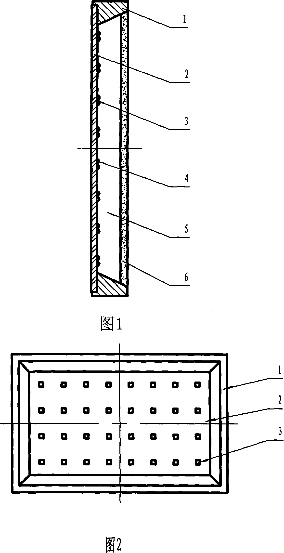
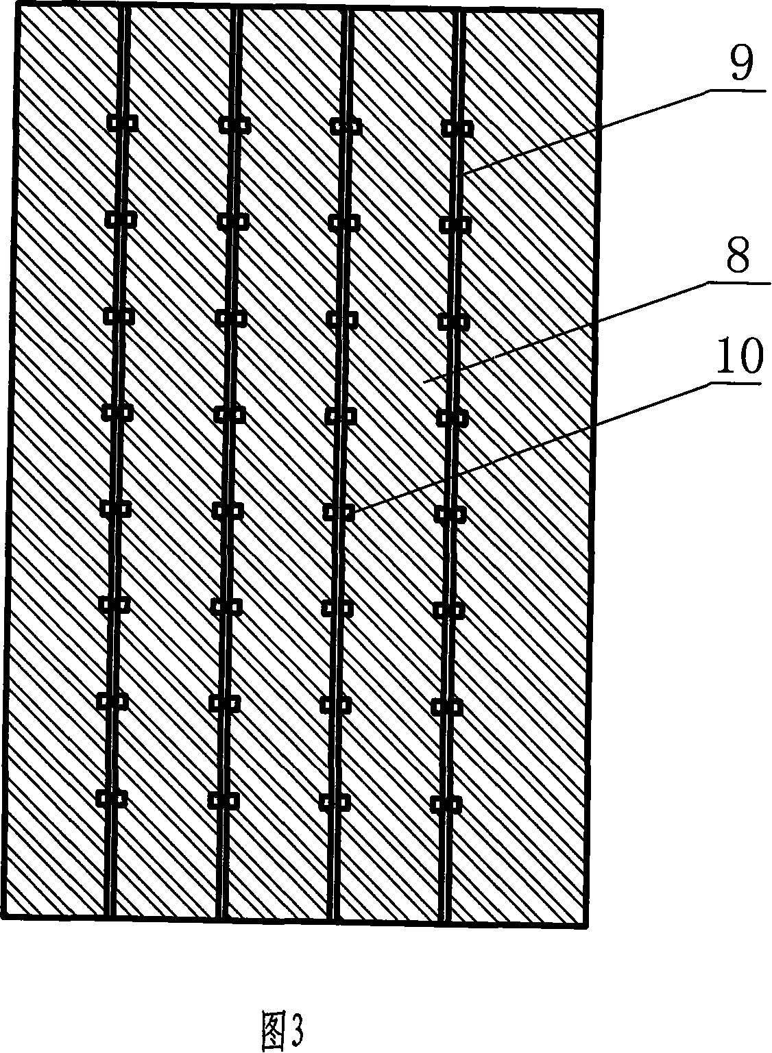
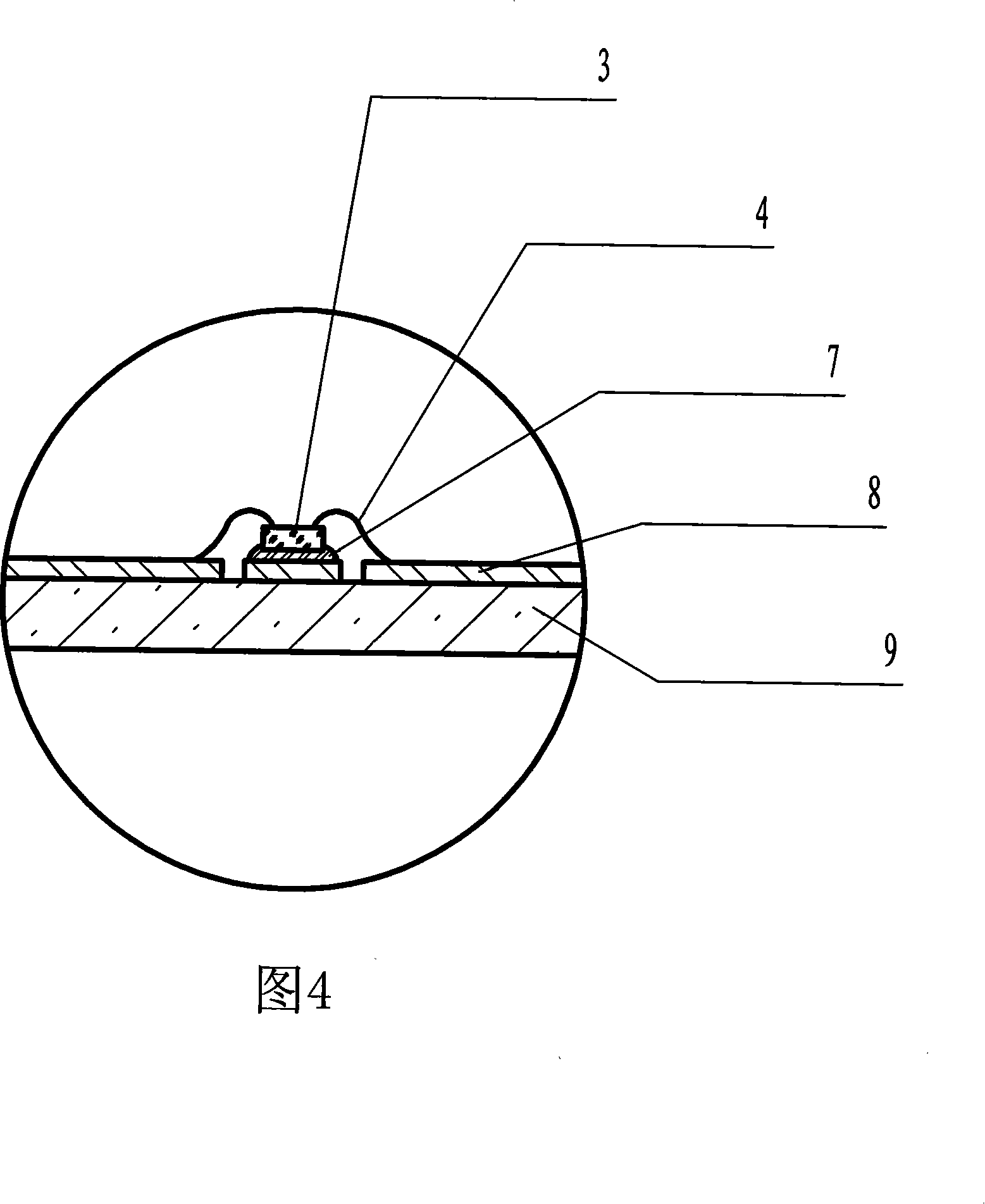
[0027] First select the chip and phosphor and design and make the circuit board. This embodiment uses a 460-465nm band blue light chip, the chip normal light intensity is 160-180mcd, the voltage range is 3.0-3.5V, the chip size is 14×14mil, and phosphor powder that can be excited by 460-465nm light is used, such as Taiwan Hongdae's TMT-00432-6065 phosphor. In this embodiment, the circuit board is designed and produced according to the requirements of power 1W and voltage 12V. As shown in Figure 3, a circuit structure with four groups connected in series and 8 chips connected in parallel in each group is adopted. In the figure, 8 is the copper clad layer of the circuit board, 9 is the substrate of the circuit board, and 10 is the pad. In this embodiment, the circuit board adopts a half-glass fiber copper-clad laminate, the pad 10 is ...


PUM


Abstract

The invention discloses a packaging method for white light LED surface light source module, which insists of processing steps such as making circuit boards, fixing crystal, bonding, packaging basic bond line and so on. The invention adopts steps: distributing multiparticulate miniwatt LED chips on a circuit board and packaging integrally to form a high power LED light source, dispersing the heat source, reducing heat productivity on a unit area, reducing heat dispersion requirement standard. Adopting white colloid as solid crystal glue can improve more than 70% of back face emergent light utilance. The basic bond line packaging makes microcosmic light source points distribute uniformly on a bigger area, reduce luminous intensity on a unit area. The light flux on a unit area of traditional LED light source is more than 100 lm/cm<2> generally, while light flux on a unit area of the invention is less than 51 lm/cm<2> generally, thereby glaring is overcame.

Description

technical field [0001] The invention relates to an LED packaging method, in particular to a packaging method for a white LED surface light source module. Background technique [0002] The application potential of LED light source in the field of white light lighting is very huge. The usual manufacturing method of white LEDs is to install blue LED chips in a bowl-shaped reflective cavity, covered with a thin layer of resin mixed with YAG:Ce phosphor powder that can produce yellow light, about 200-500nm. Part of the blue light emitted by the LED chip is absorbed by the phosphor, and the other part of the blue light is mixed with the yellow light emitted by the phosphor to obtain white light. [0003] At present, the packaging of low-power white light LEDs is mainly Φ3, Φ5, Φ10 or straw hat type and piranha. The packaging of high-power white light LEDs is mainly to package single or multiple high-power chips such as 1W and 3W on ceramic shells or aluminum substrate shells. T...

Claims


Application Information

Patent Timeline
Patent Type & Authority Applications(China)
IPC IPC(8): H05B33/10F21V19/00F21Y101/02F21Y105/16F21Y115/10
Inventor 崔泽英谷青博
Owner SHIJIAZHUANG EMPOLDER SHENTONG MACHINE ELECTRIC EMPOLDER
Why Eureka
Try Eureka