
Aerating unit for film component

A technology of aeration device and membrane module, applied in the field of water treatment, can solve the problems of complex manufacturing process, shorten the service life of components, and reduce the utilization rate of membrane filaments, so as to improve the utilization rate of membrane filaments, prolong the service life, and simplify the production process Effect

Active Publication Date: 2008-03-12
TIANJIN MOTIMO MEMBRANE TECH
View PDF0 Cites 6 Cited by
  • Summary
  • Abstract
  • Description
  • Claims
  • Application Information

AI Technical Summary

Problems solved by technology

[0003] 1. The gas directly enters the inside of the module from the end face, the uniformity of aeration is poor, the aeration effect is not good, and the cleaning effect of the membrane is affected
[0004] 2. Due to the limitations of the manufacturing process, the pores on the end face are large, the amount of air used for aeration is large, and the energy consumption is high
[0005] 3. A large amount of gas enters from the bottom, which has a greater impact on the root of the membrane filament, which may easily cause membrane filament breakage and fatigue damage, reducing the service life of the component
[0006] 4. Double-ended water production cannot be performed, and the utilization rate of membrane filaments is reduced
[0007] 5. The manufacturing process is complicated, and it is easy to form product defects

Method used


Image

  • Aerating unit for film component
  • Aerating unit for film component
  • Aerating unit for film component

Examples


Embodiment Construction

[0025] The present invention will be described in detail below in conjunction with the accompanying drawings and specific embodiments.

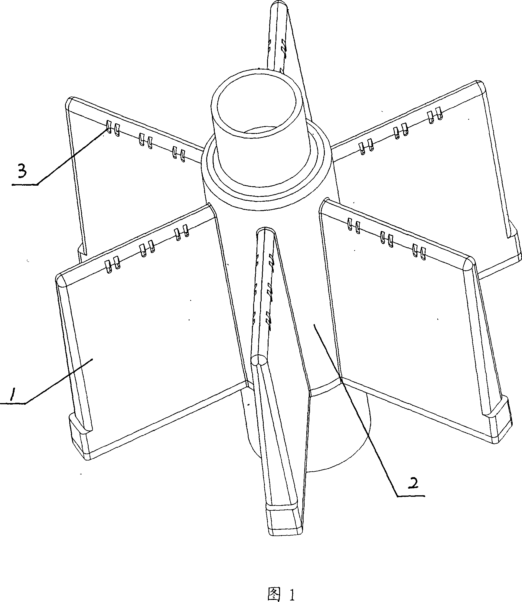
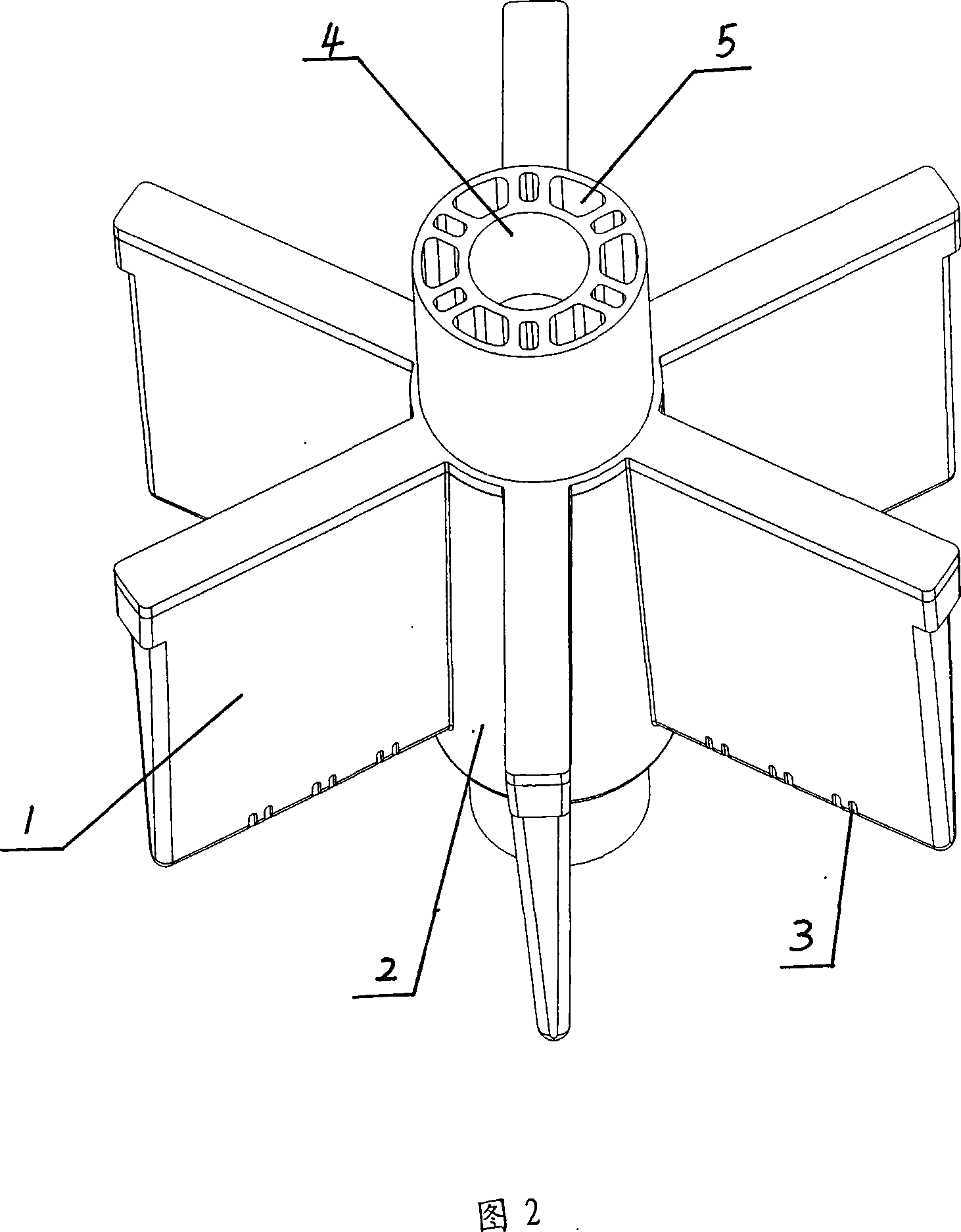
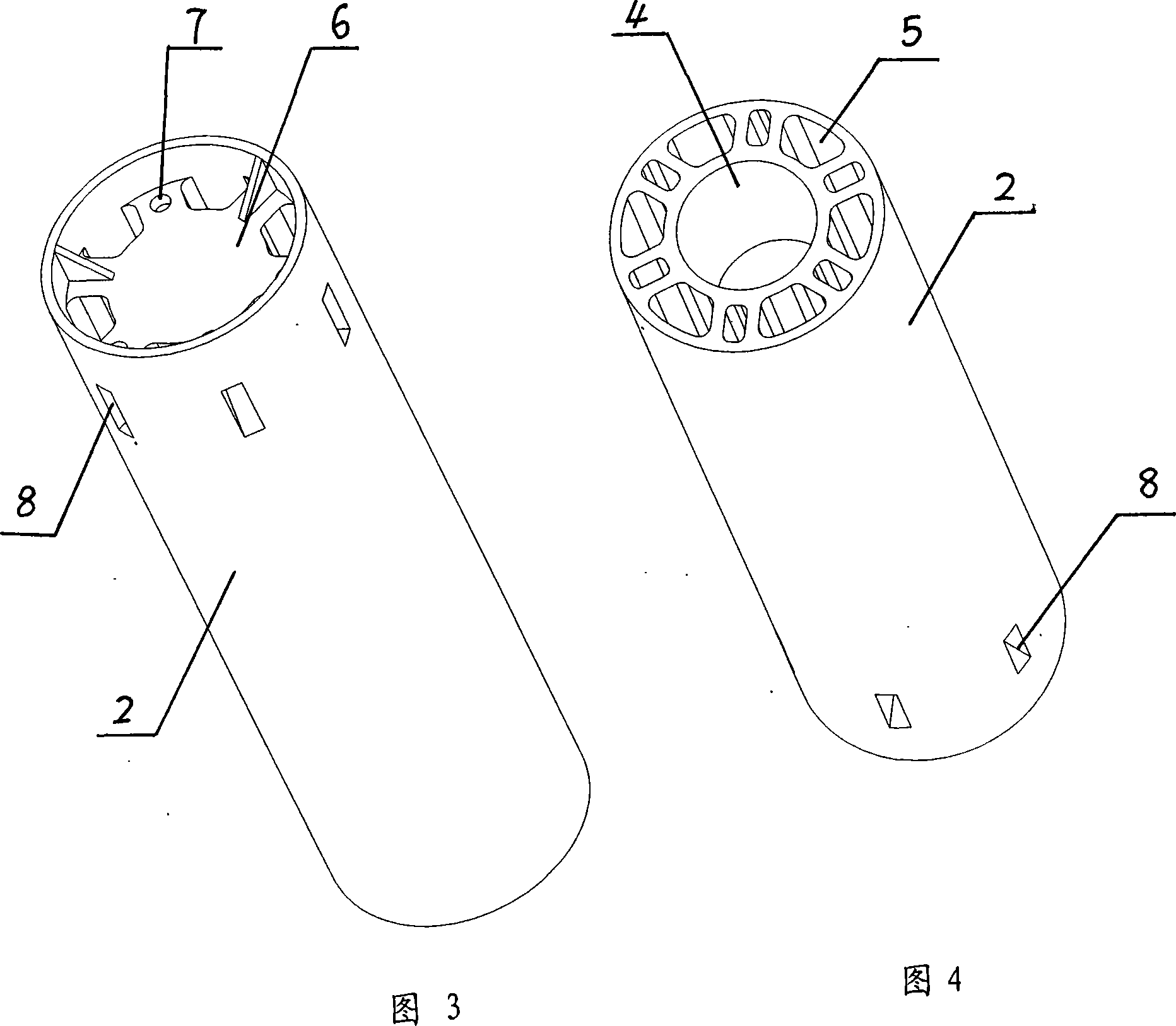
[0026] The schematic diagram of the aeration device of the present invention is shown in Figures 1-5, including an aeration body 2, an air collection chamber 4 is arranged inside the aeration body 2, and a plurality of passing aeration bodies are connected to the outside of the aeration body 2. The air holes 8 on the top are connected to the closed air chamber 1 of the air collection chamber, and each air chamber is provided with a plurality of aeration holes 3 . The number of air chambers is generally 2-20 pieces, and the number of aeration holes can be selected between 1-1000. In order to simplify the manufacturing process, the aeration body can be a hollow column, and the upper end of the hollow part is closed as an air collection chamber. The lower part of the gas collection chamber is sealed and connected with the aeration column 11 wit...


PUM


Abstract

The present invention discloses an aeration device applied to membrane components and aims at providing an aeration device which is applied to membrane components so as to lead gas to form stable airflow in the inside of the components with a good membrane cleaning effect and can prolong the service life of membrane yarn and be able to carry through to produce water at two ends. The device includes an aeration body and an air collection chamber is arranged in the aeration body. The outside of the aeration body is connected with multiple closed air chambers communicated with the air collection chamber. Each air chamber is provided with multiple aeration holes. The upper part of the aeration body is provided with a water collection chamber and multiple outlet openings are arranged in the water collection chamber. The lower end of the aeration body is provided with multiple inlet openings. The aeration body is provided with a channel to communicate the inlet openings and outlet openings. The aeration device of the present invention leads gas to form continuous and stable airflow after entering the inside of the components so as to lead the up and down aeration of the membrane yarn to be uniform. The present invention has a good pollution removing and guarantees continuous and stable application of the components. And up and down arrangement of gas is uniform and the up and down force of the membrane yarn is consistent. The present invention has prolonged the service life of the membrane yarn.

Description

technical field [0001] The invention relates to the field of water treatment, and more specifically relates to an aeration device used in a hollow fiber membrane module. Background technique [0002] Hollow fiber membrane modules are now widely used in membrane filtration treatment in various industrial production processes, such as ultrapure water for washing semiconductors, petrochemical wastewater treatment, and seawater desalination, etc. In these fields, most of them use column or curtain Type external pressure hollow fiber membrane module. At present, in the above external pressure membrane module, the gas scrubbing method is generally used to remove membrane pollution, and different manufacturers use different aeration methods. In the above-mentioned membrane modules, most of the holes are opened at the bottom of the module, and the gas enters the inside of the module through the air holes distributed on the end face of the module to form aeration. Its disadvantages ...

Claims


Application Information

Patent Timeline
Patent Type & Authority Applications(China)
IPC IPC(8): C02F3/12
CPCY02W10/10
Inventor 苗蕾于鸿来安强王海涛吴静宇王龙兴
Owner TIANJIN MOTIMO MEMBRANE TECH
Learn More