
Small power modularize solar cell component

A technology of solar cell components and solar cells, applied in the direction of electrical components, electric solid devices, circuits, etc., can solve problems such as damage, waste, and component performance degradation, and achieve the effects of increasing service life, reducing waste, and low power

Inactive Publication Date: 2008-03-12
SUN YAT SEN UNIV
View PDF0 Cites 15 Cited by
  • Summary
  • Abstract
  • Description
  • Claims
  • Application Information

AI Technical Summary

Problems solved by technology

The EVA used in this packaging method will undergo physical and chemical changes under the action of long-term sunlight, high temperature, and moisture, which will reduce the performance of the component or even damage it.
In addition, in this packaging method, many failed components are often caused by a problem with one of the cells, while the other cells are still intact, so that the entire component is damaged by one cell, causing great damage. waste
In addition, when building a photovoltaic system, the degradation of a component's performance often affects the work of the entire system. When a problem occurs, it is difficult to determine which component has the problem.

Method used


Image

  • Small power modularize solar cell component
  • Small power modularize solar cell component
  • Small power modularize solar cell component

Examples


Embodiment 1

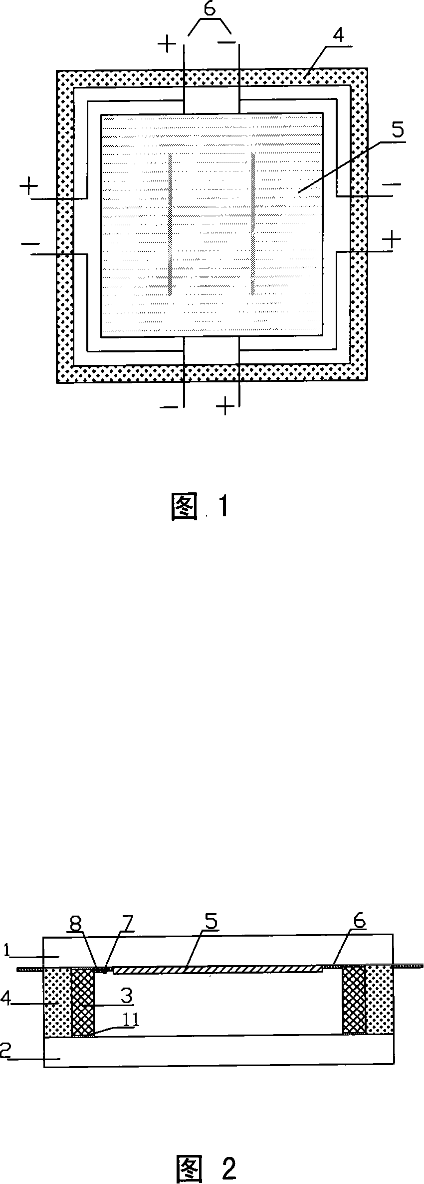
[0029] A low-power modular solar cell module as shown in Fig. 1 and Fig. 2, which includes a glass plate, a solar cell sheet 5, a bypass diode 8 and a component status display module 7 for indication, a bypass diode 8 and a component status The display modules 7 are electrically connected to the solar cells 5 respectively, and the glass plates include a top glass plate 1 and a bottom glass plate 2, and a spacer bar 3 for sealing is installed around the top glass plate 1 and the bottom glass plate 2, The spacer 3 can use aluminum spacer, stainless steel spacer, plastic spacer or some flexible spacer, spacer 3 is filled with molecular sieve desiccant or coated with glue containing molecular sieve desiccant, the spacer 3 and the top surface The glass plate 1 and the bottom glass plate 2 are all airtightly connected, and the three form a closed hollow chamber, which is filled with inert gas or evacuated, and the solar cells 5, bypass diodes 8 and component status display modules 7...

Embodiment 2

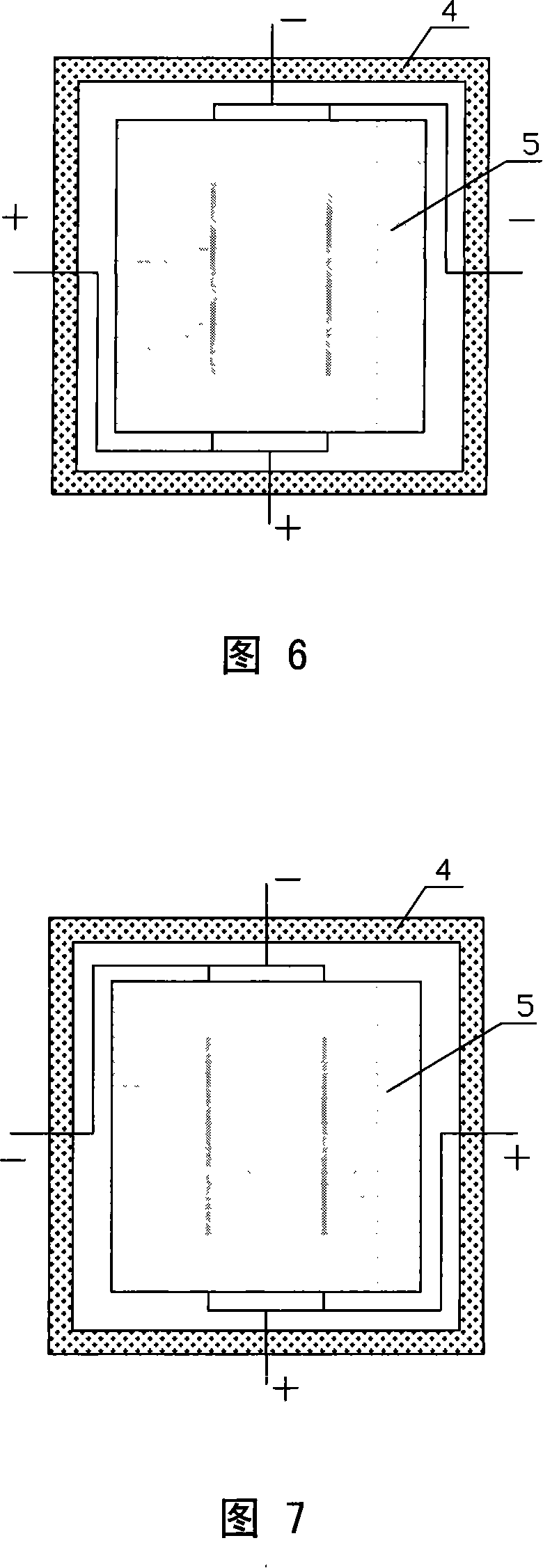
[0032] As shown in FIG. 3 , the difference between the present embodiment and the first embodiment lies in the arrangement of the positive and negative electrodes of the solar cells.

Embodiment 3

[0034] As shown in Figure 4, the difference between this embodiment and Embodiment 1 is that a spring 9 is also provided in the hollow chamber, and rubber pads 10 are placed on both ends of the spring 9, and the upper end of the spring 9 is pressed against the solar cell. sheet 5, so that the solar battery sheet 5 is close to the lower surface of the top glass plate 1, and the lower end of the spring 9 is against the upper surface of the bottom glass plate 2.


PUM


Abstract

A miniwatt modularized solar battery component is provided, which comprises glass sheet and solar battery plate with positive electrode and negative electrode. The said glass sheet contains top glass sheet and bottom glass sheet, between which the spacer bars for encapsulation are set loop-enclosed. The spacer bars are air tightly connected with the top glass sheet and bottom glass sheet, which forms an airtight fistular cavity that is filled with the inert gases or vacuumized. The said solar battery component is mounted with shunt diode and the component status display module. The solar battery plate, shunt diode and component status display module all equipped on the said fistular cavity, wherein the shunt diode and component status display module are respectively connected with solar battery plate while the positive electrode and negative electrode of the solar battery plate pass through the said spacer bars and then to be led out. The solar battery component provided in the invention can improve the flexibility of the application while extending its service life.

Description

technical field [0001] The invention relates to a solar cell assembly, in particular to a low-power modularized solar cell assembly. Background technique [0002] At present, the most widely used solar cell modules are made of glass / EVA / solar cell / EVA / TPT laminated with aluminum metal frame and junction box. (Among them, EVA-full name is ethylene vinyl acetate copolymer, the Chinese name is ethylene-vinyl acetate copolymer, which is a hot-melt adhesive; TPT is a composite film). The EVA used in this packaging method will undergo physical and chemical changes under the action of long-term sunlight, high temperature, and moisture, which will reduce the performance of the component or even damage it. In addition, in this packaging method, many failed components are often caused by a problem with one of the cells, while the other cells are still intact, so that the entire component is damaged by one cell, causing great damage. waste. In addition, when building a photovoltaic ...

Claims


Application Information

Patent Timeline
Patent Type & Authority Applications(China)
IPC IPC(8): H01L31/042H01L31/048H01L31/0203H01L25/00H01L25/16H01L31/044
CPCY02E10/50
Inventor 沈辉王响
Owner SUN YAT SEN UNIV
Learn More