Drawing network high and second harmonic wave and resonance and transient voltage restraint device

A transient overvoltage and high-order harmonic technology, applied in harmonic reduction devices, circuit devices, emergency protection circuit devices for limiting overcurrent/overvoltage, etc. Problems such as complex railway line conditions, to achieve the effect of simple structure and small equipment capacity

Inactive Publication Date: 2008-03-19
北京汇泽电力科技有限公司
View PDF0 Cites 6 Cited by
  • Summary
  • Abstract
  • Description
  • Claims
  • Application Information

AI Technical Summary

Problems solved by technology

Once the current spectrum of the EMU or electric locomotive covers the traction network resonant frequency and reaches a certain amplitude, it will excite the high-order harmonic resonance of the traction network, causing harmonic current amplification, and may generate high resonance overvoltage, which is harmful to the traction network. Hazards to the safe and stable operation of the power supply system
In addition, since EMUs and electric locomotives are fast-moving loads, they are prone to flow interruptions, and the conditions of railway lines are complex, and the operation of trains is affected by various factors. It is difficult for EMUs and electric locomotives to maintain their operating conditions for a long time. , which leads to the continuous electromagnetic transient process on the traction network. Once the network parameters and operating conditions do not match properly, it is easy to cause transient overvoltage
High-order harmonic resonance and transient overvoltage that may exist on the traction network may easily cause train parking accidents, endanger the safe operation of power supply equipment, and seriously affect the normal transportation order of the railway

Method used


Image

  • Drawing network high and second harmonic wave and resonance and transient voltage restraint device

Examples


Embodiment 1

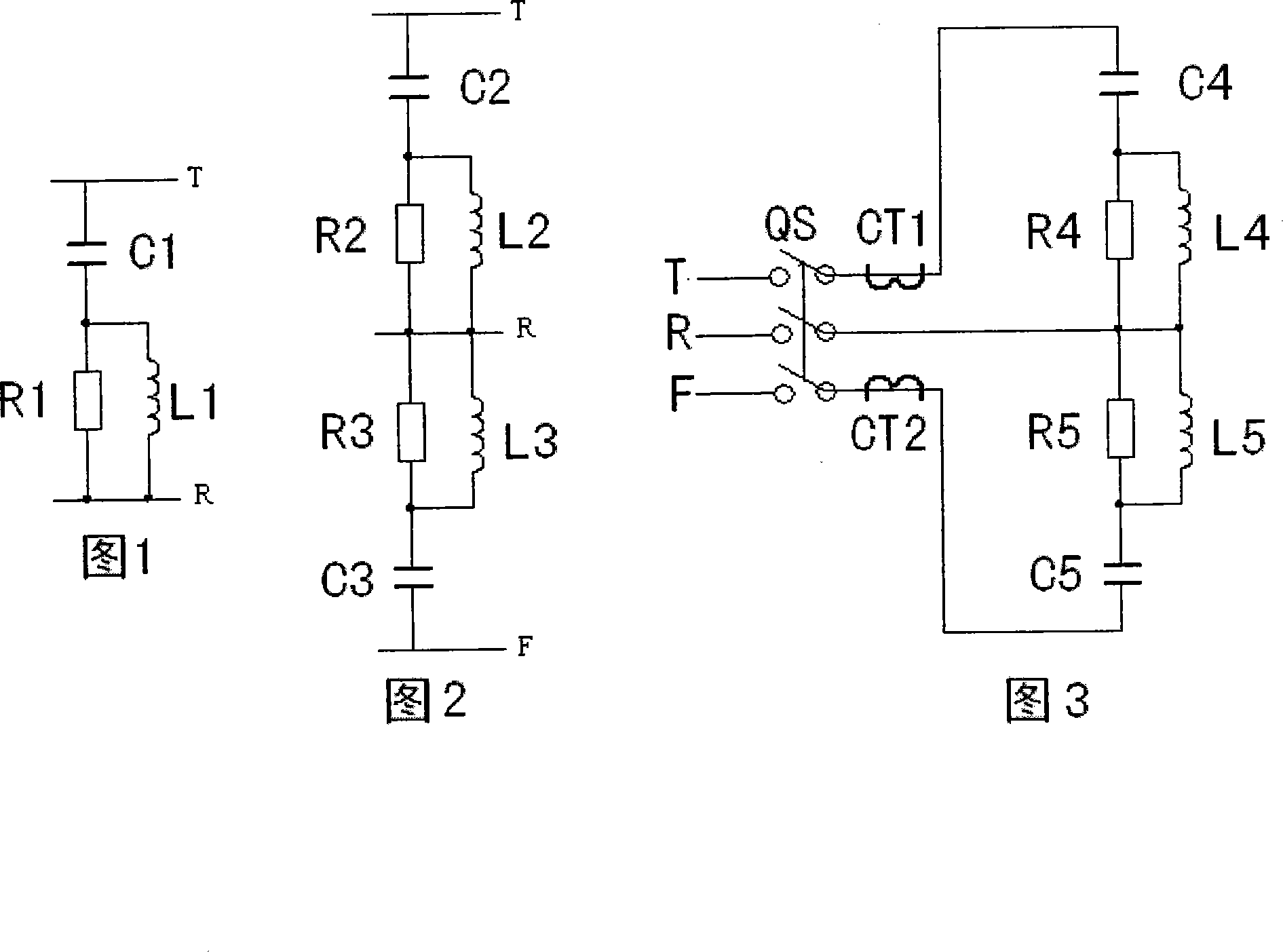
[0012] Embodiment 1: As shown in Figure 1, capacitor C1, resistor R1, and inductor L1 form a second-order damping filter circuit. The value range of C1 is 0.8-2.5μF, the value range of R1 is 100-300Ω, and the value range of L1 is 50~250mH, T stands for catenary, R stands for rail.

Embodiment 2

[0013] Embodiment 2: As shown in Figure 2, capacitor C2, resistor R2, and inductor L2 form a second-order damping filter circuit, and capacitor C3, resistor R3, and inductor L3 form another second-order damping filter circuit, and the parameters of the two circuit components take values Consistent, T stands for catenary, R stands for rail, F stands for positive feeder.

Embodiment 3

[0014] Embodiment 3: As shown in Figure 3, C4=C5=1μF, R4=R5=150 Ω, L4=L5=200mH, in the embodiment, the suppression device passes through the T and R of the three-pole circuit breaker and the 2×25kV traction network , F are connected, and the current transformers CT1 and CT2 are respectively set on the T line and the F line, and the secondary circuit is connected to the relay protection equipment, which is used for overcurrent protection of the suppression device, and the parallel voltage transformer is used for power failure. The capacitor is discharged.


PUM


Abstract

The invention relates to a higher harmonic wave resonance and transient overvoltage suppression device for an AC traction electric network of an electric railway, which comprises a circuit breaker, an isolating switch, a capacitor, a resistor, a reactor and relay protection equipment, wherein a second-order damping filter circuit is normally arranged in a subzone at the end of a feeding section or in the middle thereof; when the suppression device is used in the 25 KV traction electric network, the second-order damping filter circuit is arranged between a contact system (T) and a steel rail (R), and when the suppression device is used in the 2 is multiplied by 25 KV traction electric network with an autotransformer (AT) power supply, the two second-order damping filter circuit are used, one is arranged between the contact system and the steel rail, the other one is arranged between a positive feeder (F) and the steel rail, and parameters thereof are identical. The invention can suppress and damp the higher harmonic wave resonance and transient overvoltage by changing a topological structure and the network parameters of the traction electric network, and all the resistor, the capacitor and the inductor elements are passive, so that control equipments are not required. The invention has the advantages of simple structure, low equipment capacity, and free of maintenance.

Description

technical field [0001] The invention belongs to the technical field of electrified railways, and in particular relates to a traction network high-order harmonic resonance and transient overvoltage suppression device composed of passive resistance, inductance and capacitance elements. Background technique [0002] The EMUs and high-power electric locomotives running on my country's railways have generally adopted PWM-modulated AC-DC-AC drive circuits. Compared with the previous AC-DC rectifier electric locomotives, the harmonic content of the current EMUs and electric locomotives is significantly reduced overall, but the harmonic spectrum is wider and can reach several kHz. Since the main skeleton of the traction network is a multi-conductor transmission line, which has inherent distribution parameter characteristics, it is inevitable that the parallel distributed capacitance and series distributed impedance of the traction network will resonate with the transformer impedance...

Claims


Application Information

Patent Timeline
Patent Type & Authority Applications(China)
IPC IPC(8): H02J3/01H02H9/04B60M3/00
CPCY02E40/40
Inventor 吴命利黄足平杨少兵楚振宇刘明光
Owner 北京汇泽电力科技有限公司
Why Eureka
Try Eureka