Damper possessing axial guiding means

A guide device and damper technology, applied in the field of dampers, can solve the problems of damper damage, easy wear or aging of seals, high heating and temperature rise, etc., and achieve the effects of stable performance, reliable operation and simple structure

Inactive Publication Date: 2008-04-23
尹学军 +1
View PDF0 Cites 13 Cited by
  • Summary
  • Abstract
  • Description
  • Claims
  • Application Information

AI Technical Summary

Problems solved by technology

However, due to structural reasons, it has inherent defects: 1) Due to the static friction and sliding friction between the seal and the piston rod, and the piston and the damping cylinder, the starting resistance is relatively large, and the damping force has a poor correlation with the speed when the amplitude is small. , resulting in complex theoretical calculations and large errors; 2) A tight seal must be used, but the seal is easy to wear or age. Once the seal fails, the pressure difference cannot be established, and the damping performance will be lost rapidly; 3) The structure of the parts is complex and the number is large 1. The processing precision is high, so the cost is high; 4) The damping performance is sensitive to the processing precision and the reliability of the parts. Once the important parts such as valves fail, the damping performance will drop rapidly or fail; 5) When the damping liquid is throttling through small holes, local Due to high-pressure shearing, the instantaneous heating and temperature rise are high, and it is easy to age under long-term action, resulting in the failure of the damper; 6) The sediment and wear particles in the damping liquid affect the damping parameters and accelerate the damage of the damper; due to the above reasons, this form of Shock absorbers, except for high-quality brand-name products, generally have a low lifespan. Low-end automobile shock absorbers are even replaced every six months, causing a lot of waste of resources and polluting the environment.

Method used


Image

  • Damper possessing axial guiding means
  • Damper possessing axial guiding means
  • Damper possessing axial guiding means

Examples


Embodiment 1

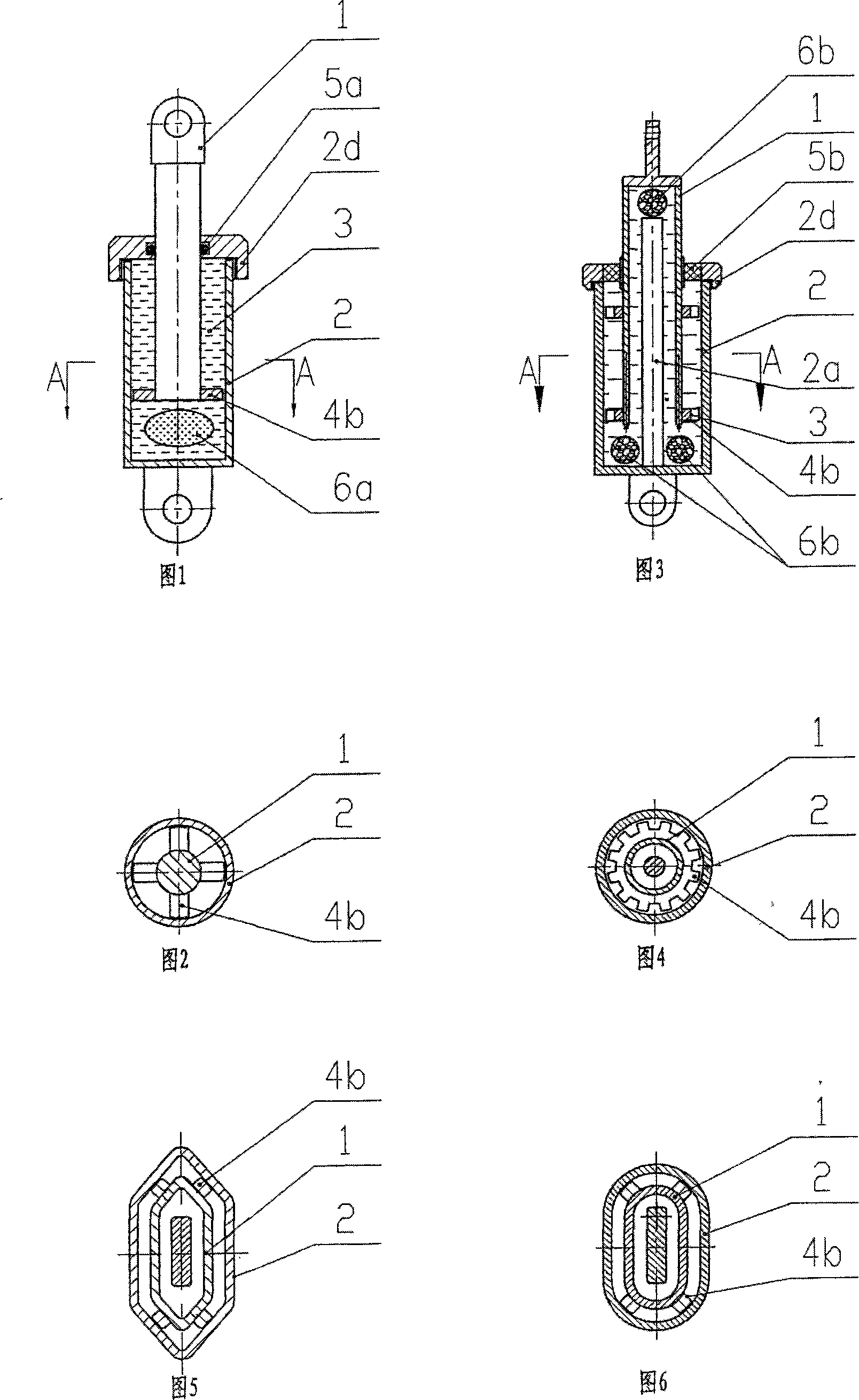
[0036] Referring to Figures 1 and 2, it includes a moving body 1 and a cylinder body 2. The moving body 1 is partially located in the cylindrical cylinder body 2 and can move axially relative to the cylinder body 2. There is a cylinder extending axially in the cylinder body. The damping chamber is filled with a viscous damping liquid 3, which is modified emulsified asphalt in a viscous liquid state at room temperature. The moving body 1 is composed of a cylindrical moving blade, and the moving blade is located in the damping chamber. , forming a shear cavity with the wall of the damping chamber, the radial dimension of the shear cavity is much smaller than its axial dimension. The end of the cylinder block is provided with a cylinder head 2d, the cylinder head cooperates with the sliding guide of the moving blade, the cylinder head is embedded with a sliding sealing ring 5a, and the end of the moving blade is fixed with a sliding guide block 4b, which is in the shape of a cross...

Embodiment 2

[0041] Referring to accompanying drawings 3 and 4, compared with embodiment 1, a cylindrical stationary vane 2a is provided in the center of the cylinder body 2, and the damping chamber is changed into an annular damping chamber. Correspondingly, the moving blade of the moving body 1 is tubular , the moving blade is located in the damping chamber, and forms a shearing chamber with the wall of the damping chamber and the stationary vane 2a. The damping chamber and the shearing chamber are filled with methyl silicone oil, and the transverse dimension of the shearing chamber is much smaller than its axial dimension. The lower part of the damping chamber is provided with an annular elastic compensator 6b, and the damping chamber at the top of the moving body is provided with an elastic compensator 6b. The elastic compensator 6b is an elastic foamed polyurethane with an airtight elastic layer on the outside.

[0042] Compared with Example 1, the moving blade of this embodiment has t...

Embodiment 3

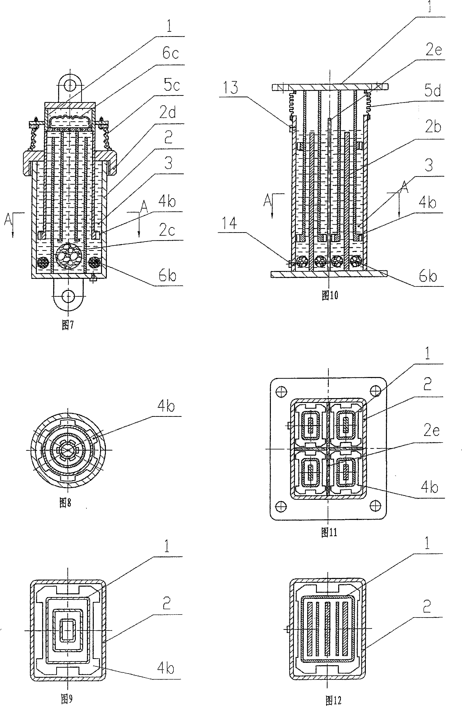
[0048] Referring to accompanying drawings 7 and 8, compared with embodiment 2, the stationary blade in the damping chamber in the cylinder body 2 is a garden tubular shape 2c, and the moving body 1 is composed of 2 circular tubular moving blades, forming 3 concentric shears. The cavity is cut, and the lower part of the damping chamber is provided with an annular elastic compensator 6b, and the elastic compensator is an elastic foamed polyurethane with an airtight elastic layer on the outside. There is a compensation chamber on the top of the moving body, and an airtight elastic film 6c is arranged in the compensation chamber, one side of which is filled with compressed air, and the other side is filled with damping liquid, which communicates with the damping chamber to compensate for the volume change of the damping chamber ; In order to increase the viscous resistance, the end of the inner moving blade is also provided with a flanging type spoiler ring piece. The end of the m...


PUM


Abstract

This invention is a divisional application, which application number is 200410075501.2. It relates to a damper. It includes cylinder body and moving body. At least parts of the moving body are in the cylinder body. At least one axial extended chamber is arranged in the cylinder body. The chamber is filled with viscous damping liquid and forms the damping chamber. The moving body is composed of moving blades that are arranged inside of the damping chamber. The moving blades and damping chamber wall form shearing cavity. The thickness dimension of the shearing cavity is far less than its axial dimension. Axial guiding device is arranged between the cylinder body and moving body. This invention is simple and reliable. It has no precise components. Thus, its cost is low. This invention also has long life span and can be used after examining and repairing.

Description

technical field [0001] The present invention is a divisional application with application number 200410075501.2, and relates to a damper, especially a shock absorber for a vehicle suspension system and a vibration-reducing energy-consuming damper for a building structure. Background technique [0002] Damper is a widely used basic component of vibration control, which is used for vibration reduction, buffering and energy dissipation of machinery, vehicles, bridges and building structures. [0003] The common damper is a hydraulic cylinder type. The piston only moves in the axial direction relative to the cylinder. It is called a single-axis damper. It is composed of a moving body, a moving body rod, a cylinder body and a seal. The moving body is generally cylindrical. The moving body is provided with a number of small holes or an appropriate radial gap is left between the cylinder and the moving body. When the moving body moves relative to the oil cylinder, the liquid seale...

Claims


Application Information

Patent Timeline
Patent Type & Authority Applications(China)
IPC IPC(8): F16F9/16F16F9/53B60G13/08E04B1/98
Inventor 尹学军
Owner 尹学军
Why Eureka
Try Eureka