Gas injection apparatus

A technology of gas injection and gas passage, applied in the direction of electrical components, plasma, gaseous chemical plating, etc., can solve the problems of large air flow, large divergence angle, and uneven spraying of air flow, and achieve large area, uniform gas distribution, The effect of simple structure

Active Publication Date: 2008-05-07
BEIJING NAURA MICROELECTRONICS EQUIP CO LTD
View PDF0 Cites 9 Cited by
  • Summary
  • Abstract
  • Description
  • Claims
  • Application Information

AI Technical Summary

Problems solved by technology

[0007] Because the included angle between the peripheral air injection holes 2 is relatively large, that is, the divergence angle is too large, there is also a large blind area 1 between each peripheral air injection hole 2, and the diameter of the peripheral air injection holes 2 is also relatively large, so there is also the inability of the air flow. Spray evenly inside the chamber, and the airflow of each beam is relatively large, it is difficult to form a uniform gas on the surface of the wafer

Method used


Image

  • Gas injection apparatus
  • Gas injection apparatus
  • Gas injection apparatus

Examples


Embodiment Construction

[0028] The gas injection device of the present invention is used to supply gas to the reaction chamber. The reaction chamber may be a reaction chamber of an inductively coupled plasma device, or a reaction chamber of other semiconductor processing equipment, or other cavities.

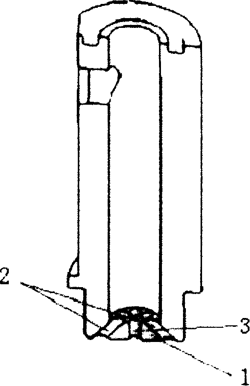
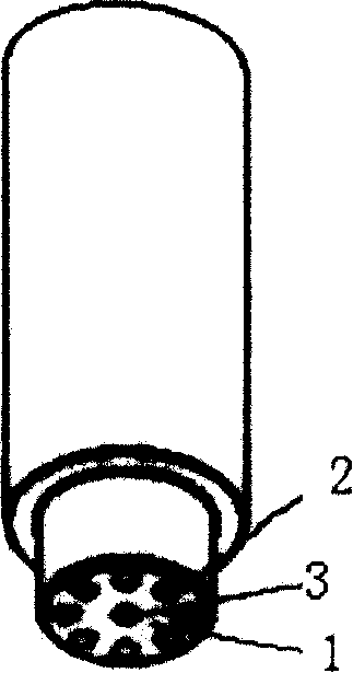
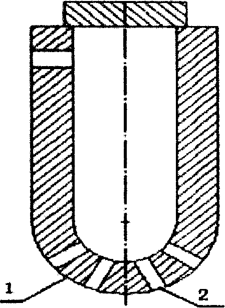
[0029] Such as Figure 4 As shown, the gas injection device of the present invention includes a body 5, a gas passage 4 is arranged in the body 5, a nozzle 6 with an arc surface is provided at the front end of the body 5, and a plurality of gas injection holes are arranged along the arc of the nozzle 6, and the gas Pass through the gas channel 4 and spray into the reaction chamber through the gas injection hole.

[0030] Such as Figure 6 As shown, the nozzle 6 is preferably hemispherical. Other arc shapes are also possible.

[0031] The diameter of the jet hole is 0.3-0.7 mm, preferably 0.3, 0.4, 0.5, 0.6, 0.7 mm, etc., preferably 0.4-0.6 mm, most preferably 0.5 mm. This size is smaller than the ...


PUM

PropertyMeasurementUnit
diameteraaaaaaaaaa
diameteraaaaaaaaaa
diameteraaaaaaaaaa

Abstract

The invention discloses a gas injection device used for feeding gas to a reaction chamber, which comprises a body, a gas channel arranged in the body, a nozzle with arch-shaped surface arranged at the front end of the body, and a plurality of orifices arranged along the arch surface of the nozzle. The diameters of the orifices are 0.3 to 0.7 mm, and the gas is sprayed into the reaction chamber through the gas channel and via the orifices. The central orifice is arranged along the central axis direction of the gas injection device, the peripheral orifices are arranged on the periphery of the central orifice, and have 0 to 90 degree included angle with the central orifice. The peripheral orifices are radiated from the central orifice to the periphery, and the radiation angle is 15 to 30 degrees. The included angle between orifices is 5 to 15 degrees. The invention has the advantages that the structure is simple, the gas injection covering area is large, and the gas is distributed evenly, thereby especially suitable for gas supply systems of semiconductor silicon wafer processing equipment, and also suitable for the gas supply in other occasions.

Description

technical field [0001] The invention relates to a gas distribution device, in particular to a gas supply device for semiconductor silicon chip processing equipment. Background technique [0002] In the manufacturing process of semiconductor wafers in the microelectronics industry, it is necessary to use plasma to perform different processes on the wafers. The plasma is generally formed by radio frequency excitation of the reactive gas ejected from the nozzle on the top of the reaction chamber, and then passed through the electrostatic chuck. The bias voltage of the plasma bombards the wafer on the chuck, thereby realizing processes such as Etch (etching) and CVD (chemical vapor deposition) on the wafer. The way the gas enters the reaction chamber directly determines the uniformity of the flow field and distribution of the gas in the chamber, which can realize that the reaction gas can evenly contact the wafer surface and have the same wafer surface pressure during the proces...

Claims


Application Information

Patent Timeline
Patent Type & Authority Applications(China)
IPC IPC(8): H01L21/00H01L21/3065H01L21/205C23F4/00C23C16/455H01J37/32H05H1/00
Inventor 魏小波
Owner BEIJING NAURA MICROELECTRONICS EQUIP CO LTD
Why Eureka
Try Eureka