
Energy-saving control method of oil pumping machine

An energy-saving control and oil-pumping unit technology, applied in the direction of AC motor control, control system, optimized efficiency control at low load, etc., to achieve the effect of increasing the number of strokes, increasing power consumption, and reducing pump leakage

Inactive Publication Date: 2008-05-07
李晓军
View PDF0 Cites 7 Cited by
  • Summary
  • Abstract
  • Description
  • Claims
  • Application Information

AI Technical Summary

Problems solved by technology

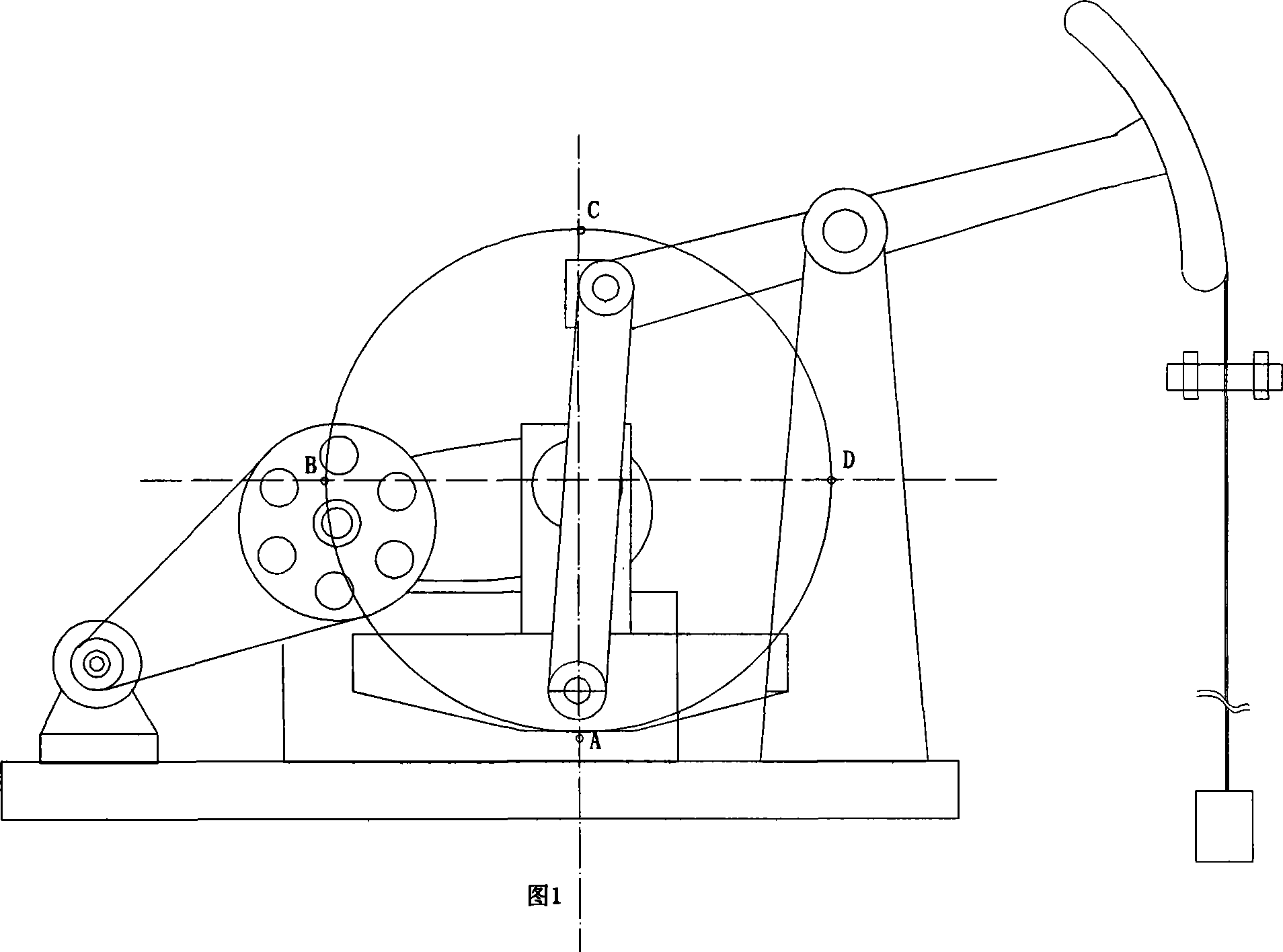
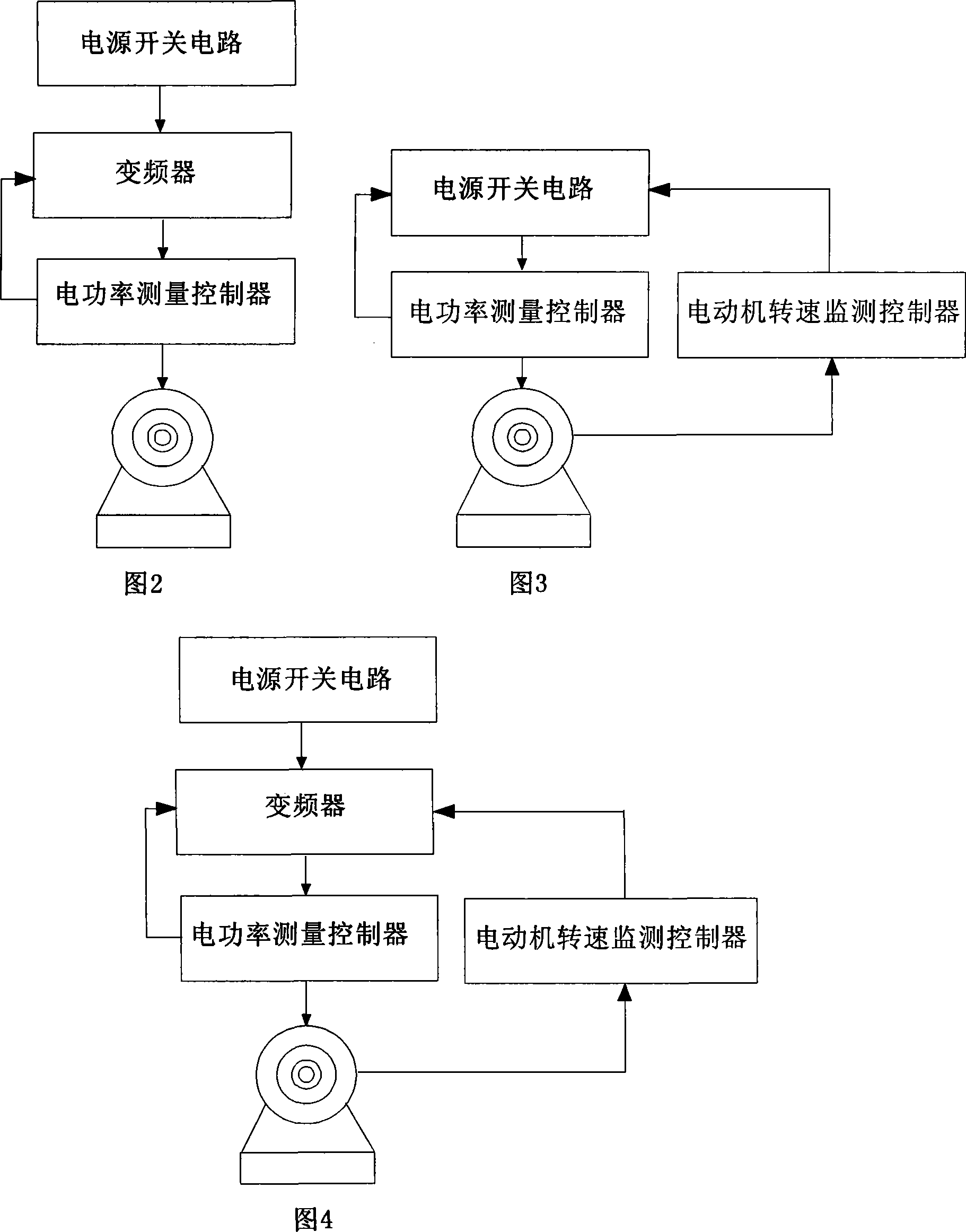
[0004] The technical problem to be solved by the method of the present invention is realized in the following three ways: 1) a frequency converter and an electric power measurement controller are set at the output end of the power switch circuit of the pumping unit, and the load, current and voltage of the motor are automatically tracked and changed Control, the control steps are: ①When the counterweight of the pumping unit moves between points C and D, and the equivalent gravity on both sides of the beam is equal, and the positive work done by the motor is about to approach zero, the electric power measurement controller will give The dynamic control signal is sent out, and the closed-loop control of the motor is controlled by the PID regulator of the frequency converter, and the real-time tracking adjustment is performed to increase the motor speed and make the motor do a little work on the reduction box to ensure that the motor does not enter the state of negative power. At this time, the sucker rod is fast Upward; ②When the counterweight moves between points A and B or close to point A under the action of inertia, the inertia consumption generated by the gravitational potential energy gradually approaches zero, and the motor starts to do positive work again, and the electric power measurement controller detects After the positive power of the motor gradually increases, the frequency converter controls the motor to decelerate. When the motor speed drops to the rated speed, the frequency converter is limited by the set frequency lower limit, and controls the motor to stop decelerating and drag the counterweight to go up again.

Method used


Image

  • Energy-saving control method of oil pumping machine
  • Energy-saving control method of oil pumping machine

Examples


Embodiment 1

[0021] The method of the present invention can avoid the inconvenience of changing the belt pulley when changing the stroke times of the pumping unit due to changes in geological conditions; the balance of the pumping unit is adjusted so that the equivalent gravity of the counterweight of the pumping unit is greater than the equivalent gravity of the donkey head load of the pumping unit , the head is light and the tail is heavy, that is, after the natural stop, the counterweight is still at the vertically lower position to set point A. (As shown in Figure 1 and Figure 2) When the pumping unit is running: when the counterweight runs near point A to point B, the motor does positive work and gradually increases to the maximum value, and then runs from point B to point C , at a certain point between D, and when the equivalent gravity on both sides of the beam is close to the same, the positive work done by the motor will gradually decrease to the minimum value. In this operating ra...

Embodiment 2

[0024] An electric power measurement controller is set at the output end of the motor power switch circuit, and a motor speed measurement controller is set between the motor and the motor power switch circuit to implement automatic tracking intermittent power supply control for the motor. The control method is: ①When the pumping unit counterweight moves Between points C and D, the equivalent gravity on both sides of the beam is equal, and when the positive work done by the motor approaches zero, the electric power measurement controller controls the motor power switch circuit to turn off the motor power supply. At this time, the sucker rod moves upward rapidly. ;②When the counterweight moves between points A and B or close to point A under the action of inertia, the inertia consumption generated by the gravitational potential energy gradually approaches zero, and when the motor speed drops to the set speed, the motor speed measurement controller Control the motor power switch c...

Embodiment 3

[0026] The method of the present invention controls the intermittent power supply of the motor by measuring the rotational speed of the motor shaft and the power consumption of the motor. When it is close to zero, the positive power detected by the electric power measurement controller is close to zero, and immediately controls the frequency converter to stop supplying power to the motor. Under the action of the gravitational inertial potential energy of the counterweight, the pumping unit runs freely downward to between points A and B (or when it moves close to point A), and when the inertia consumption generated by the gravitational potential energy gradually approaches zero, it is controlled by the motor speed measurement When the online converter detects that the motor speed drops to the original rated speed, it immediately controls the frequency converter to resume power supply to the motor and continue to run the next working cycle.


PUM


Abstract

The present invention provides the energy conservation method of a pumping unit. According to the method, a frequency converter and an electric power measurement controller are arranged at the output end of the power supply switch circuit of a motor, a motor speed measurement controller is arranged between the motor and the power supply switch circuit of the motor to automatic track and control an intermitting power supply. The control mode is as follows: {1} when the counter balance of the pumping unit moves between C and D, the equivalent gravities at two sides of a beam equal are equivalent, the positive work of the motor is almost zero, then the electric power measurement controller controls the frequency converter to shut off the power supply of the motor and a pumping rod rises rapidly; {2} when the counter balance moves between A and B or near A under the inertia effect, the inertia consumption caused by gravitational potential energy becomes none gradually, the rotating speed of the motor slows down to the set speed, the speed measurement controller controls the converter to supply power to the motor again which drives the counter balance to re-rise to perform the next work cycle.

Description

1. Technical field [0001] The invention relates to a three-phase asynchronous motor control system for pumping units widely used in oil extraction operations in the petroleum industry, especially it can be configured according to the operating state of the pumping unit (the motor is doing positive work or negative work, and the pump is running up and down). The heavy balance status automatically adjusts the motor speed in real time, maximizes the use of equipment inertial energy, reduces power consumption, increases stroke times and improves liquid extraction). 2. Background technology [0002] At present, the known electric control system of pumping unit (three-phase asynchronous motor) adopts methods such as direct, step-down, soft start, frequency converter, etc., and mainly solves the starting and protection problems of the motor. In view of the structure of the beam pumping unit, it is determined that the oil pump runs up and down once in a cycle (about 6 to 20 seconds)...

Claims


Application Information

Patent Timeline
Patent Type & Authority Applications(China)
IPC IPC(8): H02P23/02H02P27/04E21B43/00
Inventor 李晓军
Owner 李晓军
Learn More