Combined edging stirring friction welding agitator head

A technology of friction stir welding and stirring head, which is applied in the direction of welding equipment, non-electric welding equipment, metal processing equipment, etc., can solve the problems of unfavorable modification of size and practicability, waste of materials, and influence on smooth progress, so as to improve practicability and convenience Removal or replacement, the effect of improving production efficiency

Inactive Publication Date: 2008-05-14
BEIJING AVIATION MFG ENG INST CHINA AVIATION NO 1 GRP
View PDF4 Cites 53 Cited by
  • Summary
  • Abstract
  • Description
  • Claims
  • Application Information

AI Technical Summary

Problems solved by technology

[0007] Patent "A Welding Tool for Friction Stir Welding of Copper and Copper Alloys" (Application No.: 200610010553.0) In order to solve the problems of material waste, unfavorable size modification and poor practicability of the stirring head used for friction stir welding of materials with higher melting point, the design is divided into two parts: One-piece structure, consisting of a clamping body and a stirring head
[0008] However, the improved design and patent application around the friction stir we...

Method used


Image

  • Combined edging stirring friction welding agitator head
  • Combined edging stirring friction welding agitator head
  • Combined edging stirring friction welding agitator head

Examples


Embodiment 1

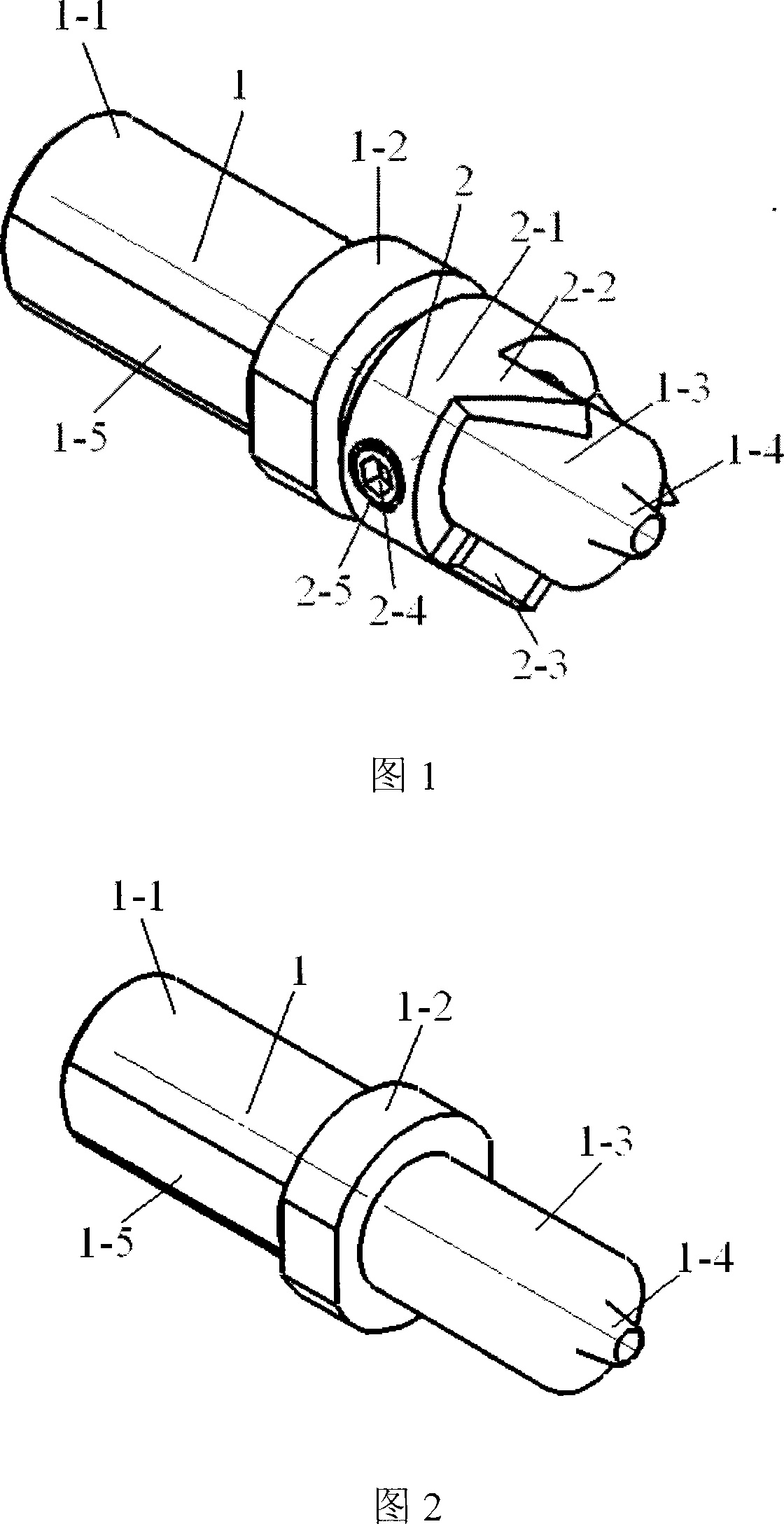
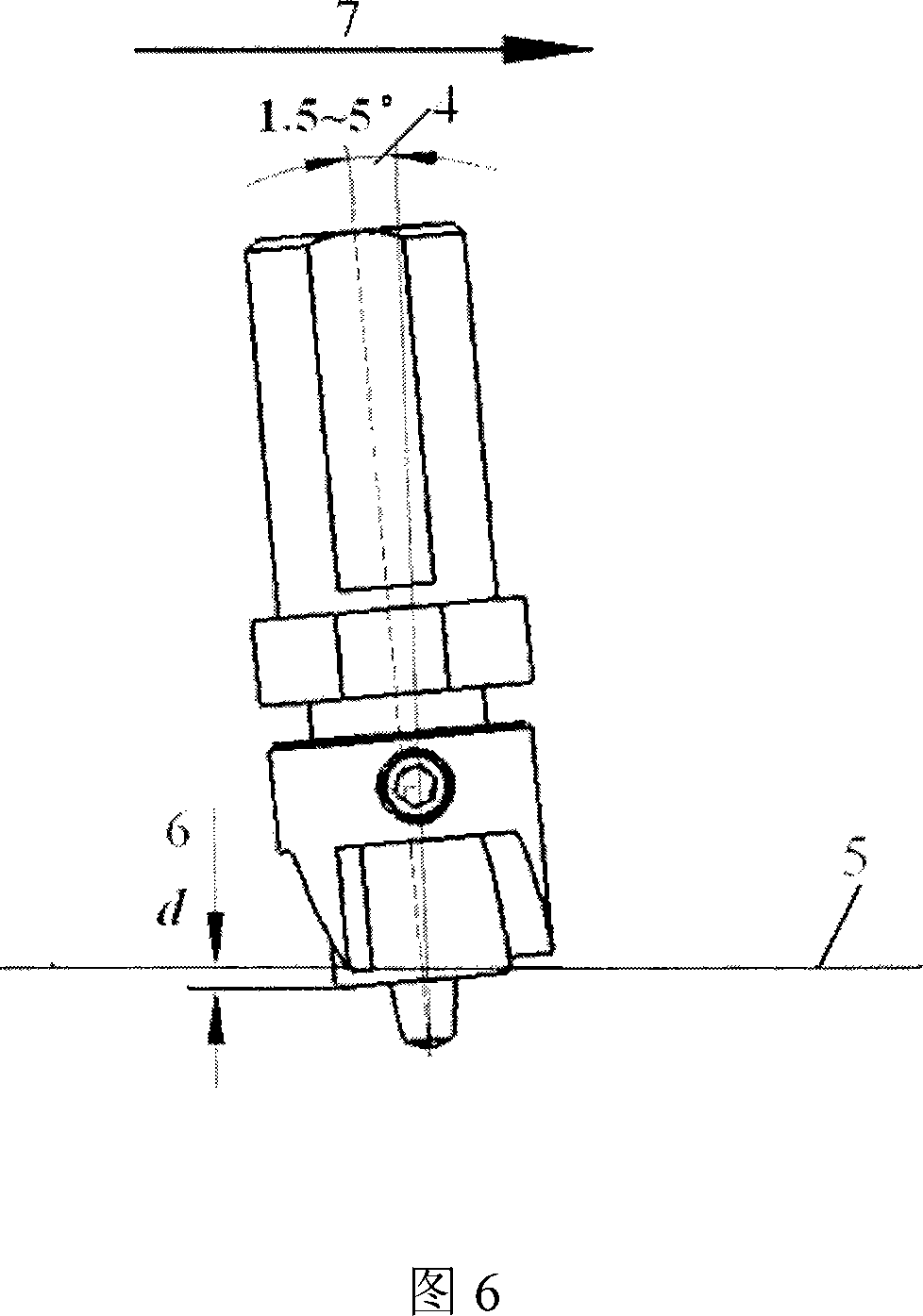
[0027] This embodiment will be described with reference to FIG. 1 , FIG. 2 , FIG. 3 , FIG. 4 , and FIG. 5 . In this embodiment, the welding parameters of the friction stir welding are that the welding inclination 4 is 1.5°, and the indentation 6 of the stirring head relative to the surface 5 of the material to be welded is 0.15 mm. The friction stir welding stirring head is a split structure, which consists of a stirring head base and a cutting tool body. The stirring head matrix includes clamping poke 1-1, shoulder 2, shaft shoulder 1-3 and stirring needle 1-4 and so on. Cutting tool body is made up of installing ring 2-1, cutting tool seat 2-2, cutting blade 2-3 and set screw 2-4 etc. The clamping poke 1-1 of the stirring head base is milled with a clamping plane 1-5, which is fixed on the main shaft of the friction stir welding machine with set screws, and screws of different specifications can be selected according to specific conditions to provide sufficient fastening fo...

Embodiment 2

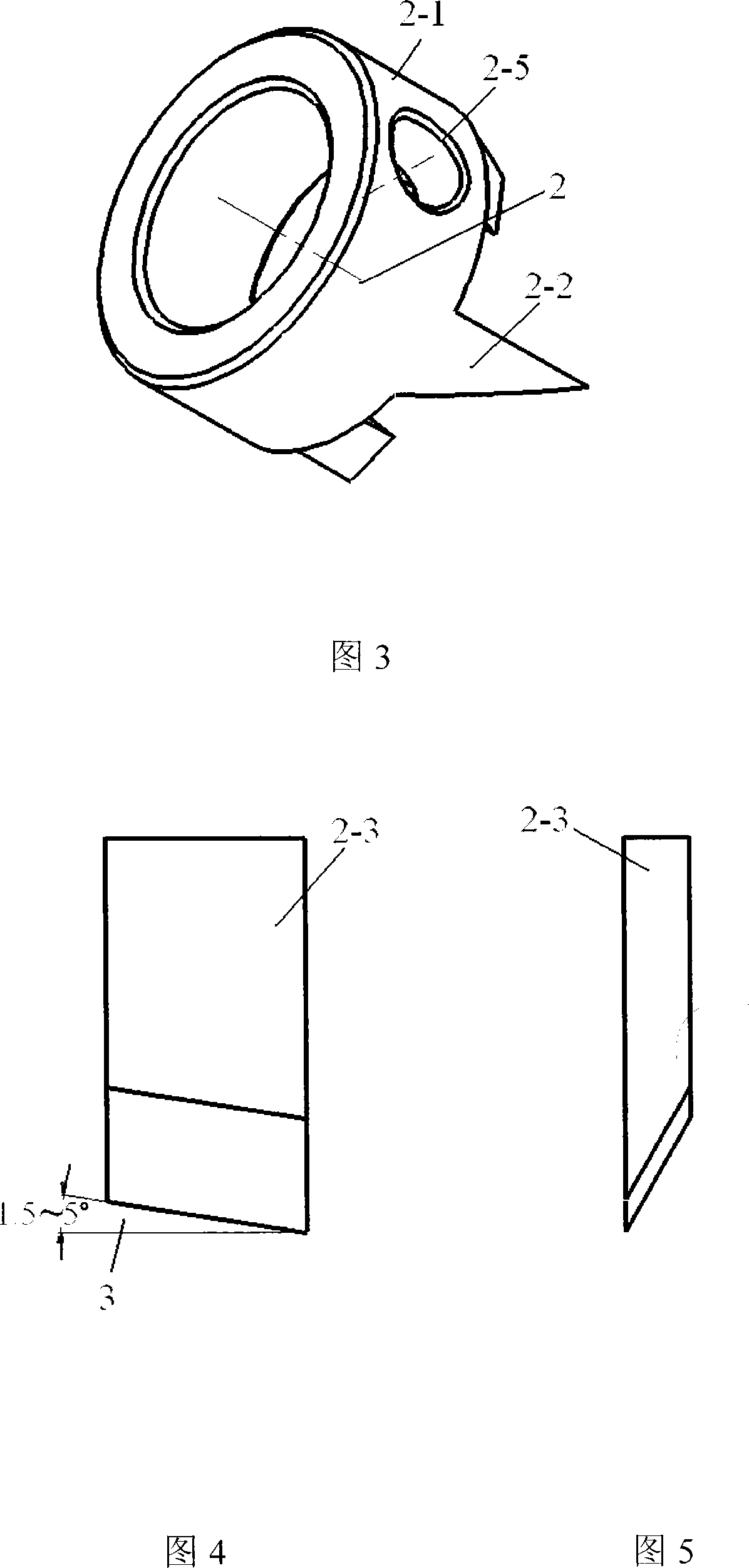
[0029] This embodiment will be described with reference to FIG. 5 . In this embodiment, the welding parameters of the friction stir welding are that the welding inclination 4 is 5°, and the indentation 6 of the stirring head is 0.1 mm. The main structural form of the combined deflashing mixing head proposed by the present invention adopted in this embodiment is the same as that of Embodiment 1, the difference is that the cutting tool body has two cutting tool seats, which are symmetrical along the circumferential direction of the installation ring Distribution, one side of the cutting tool seat is a slope, the slope angle is 85°, the slope is inlaid with cutting blades 2-3, the blade surface slope angle 3 is 5°, adjust the cutting body to move up and down along the axis of the mixing head, so that the cutting blade The shoulder edge distance of the noodle stirring head is 0.1mm.

Embodiment 3

[0031]This embodiment will be described with reference to FIG. 2 and FIG. 5 . In this embodiment, the material 5 to be welded by friction stir welding is titanium alloy, and the welding direction 7 is shown in FIG. 5 . The welding parameters are that the welding inclination angle 4 is 2.5°, and the indentation amount 6 of the stirring head is 0.08mm. The main structural form of the combined deflashing stirring head proposed by the present invention used in this embodiment is the same as that in Embodiment 1, except that the stirring head base 1 shown in FIG. 2 is a tungsten-rhenium superalloy material. The cutting tool body has 4 cutting tool holders, which are evenly distributed along the circumferential direction of the installation ring. One side of the cutting tool holder is a bevel, and the inclination angle of the bevel is 65 degrees. 2.5°, adjust the cutting tool body to move up and down along the axis of the mixing head, so that the distance between the edge of the cu...


PUM


Abstract

The invention relates to a combined type deburring stirring-friction welding stirrer head used for stirring-friction welding. The stirrer head is a combined type structure, comprising a stirrer head base and a cutter body. The stirrer head base comprises a clamping handle, a support shoulder, a shaft shoulder and a stirring pin. The cutter body comprises an installation ring, a blade holder, a tool blade, a tightly fixed bolt and a thread through-hole; the cutter body is sleeve-jointed with the shaft shoulder of the stirrer head and is fixed through the tightly fixed bolt. One surface of the blade holder is inclined with an inclination angle of 30 to 85 degree corresponding to the axial direction of the stirrer head, and the other surface is flat. The tool blade is embedded on the inclined surface, the lower end face of which is a cutting edge. An inclination angle matched with the friction welding drift angle is formed on surface of the cutting edge. The invention has the advantages of efficiently eliminating the burr of the friction welding, achieving high-quality stirring friction welding joint with flat and smooth surface, enabling to be used as ordinary ones.

Description

technical field [0001] The invention relates to a combined type deflashing friction stir welding stirring head for friction stir welding. Background technique [0002] The basic principle of friction stir welding is described in the patent US5460317. In the friction stir welding process, the workpiece is in a thermoplastic state by using the frictional heat generated between the stirring head (FSW Tool) and the workpiece. The stirring head rotates at a high speed and moves forward, and the metal in a thermoplastic state is continuously transferred from the front end to the rear end , Through the extrusion joint action of the shoulder, a dense weld is formed. Stirring head is the core part of friction stir welding technology. It is used to provide the heat required in the friction stir welding process. It is the carrier for the directional transfer of thermoplastic materials in the weld area, and it is also a tool for the diffusion connection of thermoplastic materials and s...

Claims


Application Information

Patent Timeline
IPC IPC(8): B23K20/12B23K20/26
Inventor 栾国红李光董春林栾志芳
Owner BEIJING AVIATION MFG ENG INST CHINA AVIATION NO 1 GRP
Why Eureka
Try Eureka