
Auxiliary heating micro-device bending forming method and device based on laser

A bending forming, laser-assisted technology, applied in the direction of microstructure devices, chemical instruments and methods, optical components, etc., can solve the problems of small application range, uneven material flow, complex mold structure, etc.

Inactive Publication Date: 2008-05-14
JIANGSU UNIV
View PDF4 Cites 25 Cited by
  • Summary
  • Abstract
  • Description
  • Claims
  • Application Information

AI Technical Summary

Problems solved by technology

[0007] 1. Purely using the temperature gradient effect of the material to achieve micro-bending, the controllability is poor, and only miniature parts with simple shapes can be formed, and the precision of the formed workpiece is not high
[0008] 2. Due to the influence of size effect, the cold forming process is limited in the field of microplastic forming, and the influence of material type and grain size makes the material flow uneven during the deformation process of microforming
[0009] 3. Superplastic micro-forming has special requirements on the materials of micro-devices, which requires materials with superplasticity, and the scope of application is small
[0010] 4. At present, the heating in the microplastic forming system mostly adopts indirect heating or contact heating, such as heating the mold to make the workpiece reach the required temperature, which not only makes the structure of the mold complex, but also the temperature is difficult to control, the heating time is long, and the efficiency is low
[0011] 5. The electrochemical method can only form micro devices with relatively simple structure, the forming cycle is long, the cost is high, and it is not suitable for mass production

Method used


Image

  • Auxiliary heating micro-device bending forming method and device based on laser
  • Auxiliary heating micro-device bending forming method and device based on laser

Examples


Embodiment Construction

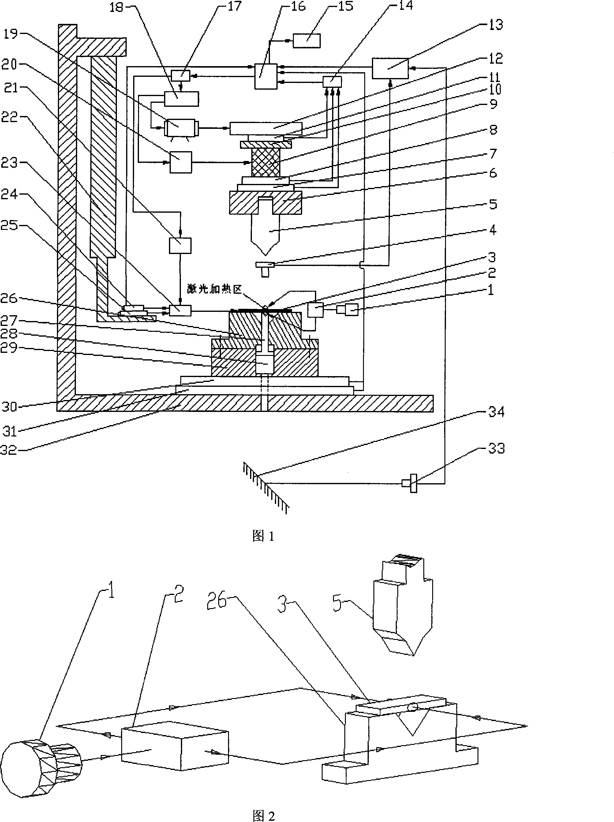
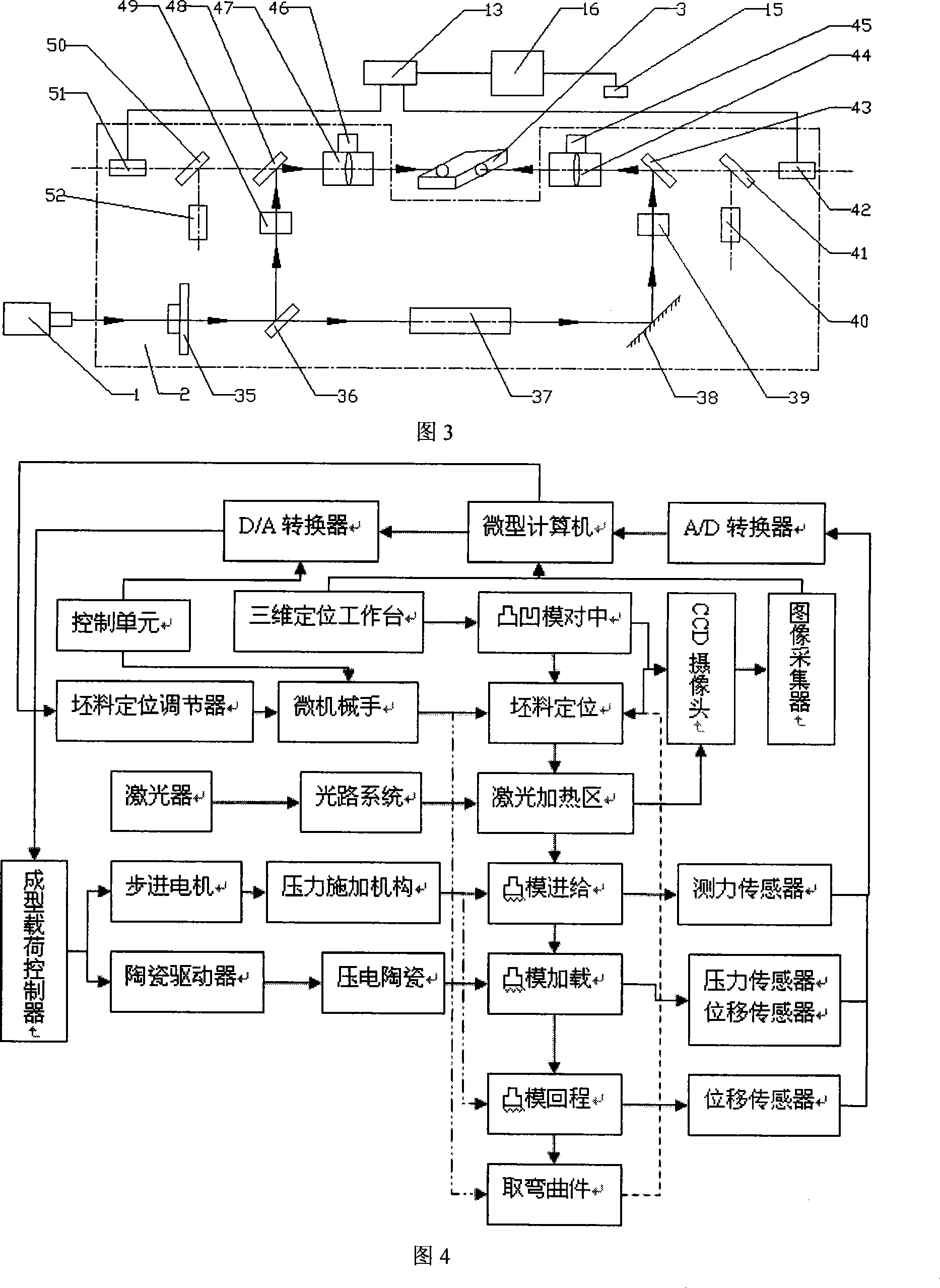
[0035] Taking the micro-bending forming of V-shaped parts as an example, the details and working conditions of the specific device proposed by the present invention will be described in detail in conjunction with Fig. 1 , Fig. 2 , Fig. 3 and Fig. 4 .

[0036] The micro-device bending forming device based on laser-assisted heating proposed by the present invention includes a mounting platform, a punch and a die centering component, a micro-bending component, a feeding mechanism, a loading mechanism, a workpiece positioning component, a laser heating system and a control system eight parts. The installation platform is composed of a support frame 22 installed under the left arm of the base 32; the centering assembly of the punch and die is composed of a mirror 34, a CCDII 33, a three-dimensional coarse adjustment positioning worktable 31, and a three-dimensional fine adjustment positioning workbench 30 to realize the punch 5 and the centering of the die 26; the micro-bending for...


PUM


Abstract

Micro-device bending forming method and device based on laser-assisted heating, involving micro-device manufacturing and micro-plastic forming technology, suitable for forming materials that are difficult or impossible to form by conventional micro-bending methods. The device includes a mounting platform, punch and die alignment Components, micro-bending forming components, feeding mechanism, loading mechanism, workpiece positioning components, laser heating system and control system, the laser beam emitted by the laser passes through the external optical path system to simultaneously perform non-contact quasi-static heating on both sides of the tiny workpiece, using laser The heat conduction makes the blank reach the forming temperature range; the laser heating system is combined with the micro-bending forming component, and the feeding and return of the punch is realized by the stepping motor drive, and the punch is loaded on the workpiece by the piezoelectric ceramic micro-driver, and the micro-bend is completed. Bending of devices. The invention reduces the influence of the temperature gradient on the forming precision. The device has reasonable design, simple process and good controllability, and is suitable for industrialized production.

Description

technical field [0001] The invention relates to the technical field of manufacturing and microplastic forming of micron-scale devices, in particular to a method and device for bending and forming of micro devices based on laser-assisted heating, which is suitable for bending and forming of micro metal devices, especially for conventional micro bending The method provides micro-forming of materials that are difficult to form or cannot be formed, and is suitable for low-cost mass production of micro-curved devices. Background technique [0002] With the development of science and technology, the equipment tends to be miniaturized. Micro devices have broad application prospects in medical bioengineering, micro robots, sensors and other industries. Especially with the further development of MEMS and aerospace technologies, the demand for micro parts of various materials At the same time, new requirements are put forward for the processing technology, processing cost and batch si...

Claims


Application Information

Patent Timeline
IPC IPC(8): B81C5/00B21D11/20B23K26/02B23K26/073G02B27/10B81C99/00
Inventor 许桢英王匀董培龙戴亚春朱永书陆广华杨昆吕盾蔡兰袁国定
Owner JIANGSU UNIV
Learn More