Grid polarizing film, method for manufacturing grid polarizing film, optical laminate, method for manufacturing optical laminate, and liquid crystal display apparatus
An optical laminate, polarized optics technology, applied in optics, polarizing elements, nonlinear optics, etc., can solve the problems of uniform optical characteristics, difficult to control the width and shape of metal cracks, etc., to improve brightness and polarization separation performance Excellent, improve the effect of utilization efficiency
- Summary
- Abstract
- Description
- Claims
- Application Information
AI Technical Summary
Problems solved by technology
Method used
Image
Examples
Embodiment 1
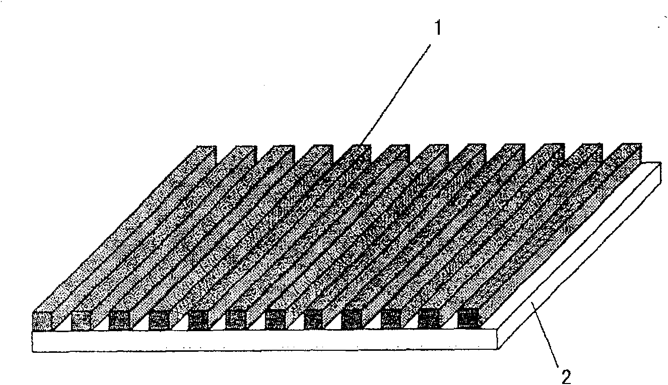
[0177] Embodiment 1 (manufacture of long strip grid polarizing film 1)
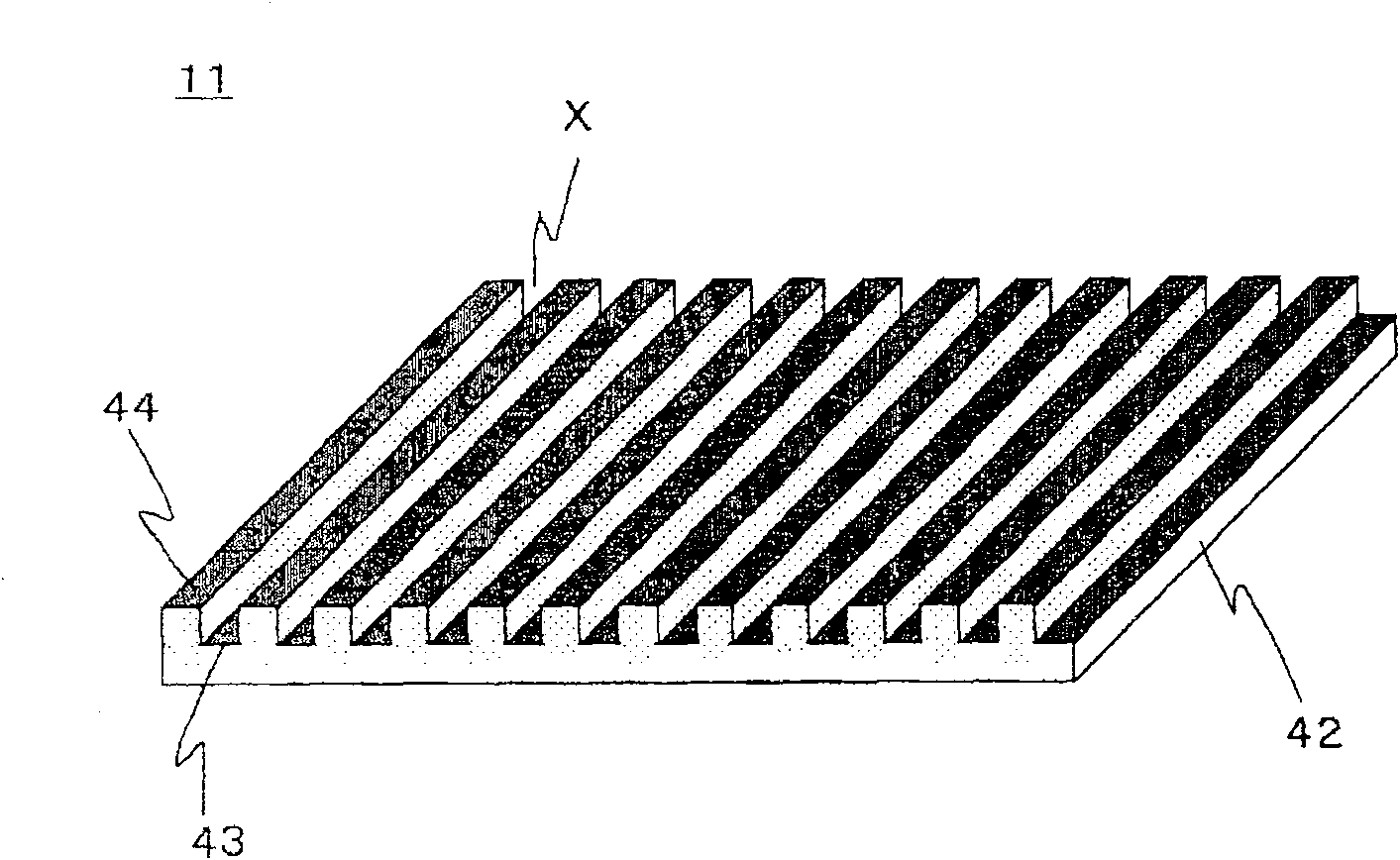
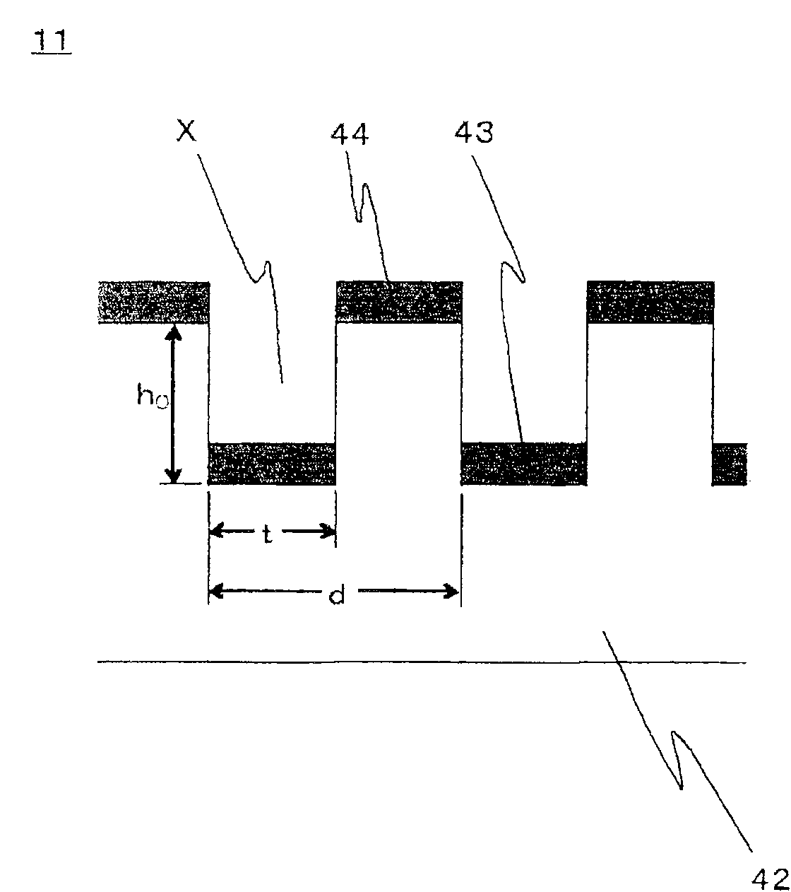
[0178] Dimensions brazed on a shank made of SUS of 8 mm x 8 mm x 60 mm using a focused ion beam processing device (concentrated ion beam processing device) (Seiko Instruments (Seiko Instruments) Co., Ltd., SMI3050) The 0.2mm×1mm surface of a cubic single crystal diamond of 0.2mm×1mm×1mm is processed by an argon ion beam for focused ion beam processing, and parallel 0.1μm-wide and 0.2μm-long sides are engraved on a 1mm-long side with a width of 0.1μm and a depth of 0.1μm. A groove of 0.1 μm was formed, and 1,000 linear protrusions of 0.1 μm in width and 0.1 μm in height were formed at a pitch of 0.2 μm to produce a cutting tool.
[0179] Nickel-phosphorus electroless plating with a thickness of 100 μm is applied to the entire peripheral surface of a cylindrical stainless steel SUS430 roller with a diameter of 200 mm and a length of 150 mm. Cylinder grinding disc (Studer (スチユ一ダ) company, precision cylinder...
Embodiment 2
[0186] Embodiment 2 (manufacture of long strip grid polarizing film 2)
[0187] Except that base film B manufactured by polycarbonate (Teijin Chemicals, Panlite (panlite) K-1300Y) manufactured by casting method (Kiyast method) was used instead of base film A, a long strip was obtained in the same manner as in Example 1. Grid polarizing film2. In addition, the in-plane average retardation of the base film B at a wavelength of 550 nm was 8 nm, the in-plane retardation deviation in the width direction and the longitudinal direction was ±2 nm, and the optical axis deviation was ±8°.
[0188] The absorbing polarizing film obtained in Example 1 and the strip-shaped grid polarizing film 2 obtained above were successively pulled out from the roll, and at the same time, an adhesive layer formed by using a polyurethane adhesive was bonded to one side of the absorbing polarizing film. A long strip-shaped grid polarizing film is laminated on top, and a long strip-shaped protective film m...
Embodiment 3
[0203] Embodiment 3 (manufacture of strip-shaped grid polarizing film 3)
[0204] Using a focused ion beam processing device (Seiko Instruments Co., Ltd., SMI3050), brazed on a shank made of SUS with a size of 8 mm x 8 mm x 60 mm, the cubic single crystal diamond with a size of 0.2 mm x 1 mm x 1 mm was brazed. On the 0.2mm×1mm surface, the focused ion beam processing is performed by argon ion beams, and parallel grooves with a width of 50nm and a height of 60nm are carved on the side of 1mm long at a distance of 130nm, and grooves with a width of 80nm and a height of 60nm are formed at a distance of 130nm. The linear protrusions are used to make cutting tools.
[0205] Nickel-phosphorus electroless plating with a thickness of 100 μm is applied to the entire peripheral surface of a cylindrical stainless steel SUS430 roller with a diameter of 80 mm and a length of 125 mm, and then a cutting tool with linear protrusions and a precision cylinder manufactured previously are used G...
PUM
| Property | Measurement | Unit |
|---|---|---|
| glass transition temperature | aaaaa | aaaaa |
| height | aaaaa | aaaaa |
| surface roughness | aaaaa | aaaaa |
Abstract
Description
Claims
Application Information
 - R&D
- Intellectual Property
- Life Sciences
- Materials
- Tech Scout
- Unparalleled Data Quality
- Higher Quality Content
- 60% Fewer Hallucinations
Browse by: Latest US Patents, China's latest patents, Technical Efficacy Thesaurus, Application Domain, Technology Topic, Popular Technical Reports.
© 2025 PatSnap. All rights reserved.Legal|Privacy policy|Modern Slavery Act Transparency Statement|Sitemap|About US| Contact US: help@patsnap.com


