Transmittance pulsation method granule measuring method and its device

A measurement method and technology of transmittance, applied in the field of particle measurement method and device of transmittance pulsation method, capable of solving problems such as difficult data processing and low measurement accuracy

Inactive Publication Date: 2008-05-28
UNIV OF SHANGHAI FOR SCI & TECH
View PDF0 Cites 19 Cited by
  • Summary
  • Abstract
  • Description
  • Claims
  • Application Information

AI Technical Summary

Problems solved by technology

[0011] The purpose of the present invention is to extend the measurement range of particle size on the basis of Gregory's particle measurement technology, and to solve the problems of difficult data processing and low measurement accuracy of Gregory's method.

Method used


Image

  • Transmittance pulsation method granule measuring method and its device
  • Transmittance pulsation method granule measuring method and its device
  • Transmittance pulsation method granule measuring method and its device

Examples


Embodiment 1

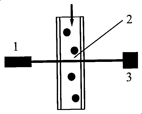
[0095] Depend on Figure 4 As shown, the narrow beam generator is composed of a laser 19 for generating parallel beams, a beam expander 22 , and a convex lens or lens group 23 . The beam emitted by the laser 19 passes through the beam splitter 20 and the beam expander 22, and then converges through the convex lens or lens group 23 to obtain a narrow beam in the Rayleigh region near the focal point. The transmitted light after the narrow beam passes through the measurement area 2 is received by the photodetector 3 after passing through the receiving lens 24 . A beam splitter 20 and a reference light detector 21 are used to monitor fluctuations in incident light intensity.

Embodiment 2

[0097] Depend on Figure 5 As shown, it includes a laser 19, a beam splitter 20, a reference light detector 21, and a beam expander 22. The narrow beam generator in this embodiment is composed of a diaphragm or an optical fiber arranged at the optical signal transmitting end and the optical signal receiving end. A narrow beam is obtained by a diaphragm or an optical fiber arranged in the direction of propagation of the broad beam emitted by the laser. The aperture is set as a front aperture 25 and a rear aperture 26, both of which can be selected or used in combination. The wide beam emitted by the laser 19 passes through the front aperture 25 to form a narrow beam, and the transmitted light after passing through the measurement area 2 is received by the photodetector 3 or the transmitted light after the wide beam emitted by the laser 19 passes through the measurement area 2 passes through the rear aperture 26 is received by photodetector 3.

Embodiment 3

[0099] Depend on Image 6 As shown, it includes a laser 19 , a beam splitter 20 , a reference light detector 21 , a beam expander 22 , a measurement area 2 and a photodetector 3 . The characteristic is that the narrow beam generator described in this embodiment consists of a laser 19, a beam splitter 20, a beam expander 22 and a narrow beam guide using a microaperture diaphragm or an optical fiber placed in front of the transmitted light detector 3 27 or composed of a laser generating parallel light beams and a micro-element signal detector, the micro-element photodetector is composed of a photodetection unit made of silicon light film material with a small light-receiving area.

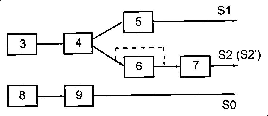
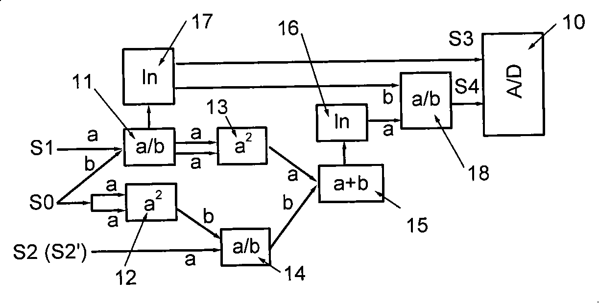
[0100] Depend on figure 2 , image 3 As shown, the signal processing device includes an analog signal processor and a signal subsequent processor.

[0101] Described analog signal processor is made up of amplifier, low-pass filter, high-pass filter and root-mean-square RMS processor, and the tran...


PUM


Abstract

The invention discloses a method and a device for measuring particles through a transmitting pulsation method. Narrow beams are eradiated on flowing particles, and a transmitting pulsation signal is produced. A photodetector is used to check, an analog circuit is adopted to process the signal, thereby requirements for collecting speed, data collecting quantity, storing quantity, and processing quantity are lowered, data processing time is shortened, and real-time measurements can be realized. Referencing optical detection is added and used to obtain information about incident optical intensity changes and perform correcting effects, interference inferences to measuring results due to light source instability can be avoided and equal particle diameter and particle density can be tested simultaneously. Sizes of the particle diameter and beam cross-sections aren't limited to Gregory method, particle diameter range of testing particles is large, The invention can be used in many fields as scientific research, production and processing control of chemical energy, environmental protection, water quality detection, particle measurement, and the like.

Description

technical field [0001] The invention relates to a measurement method and device capable of simultaneously measuring the average particle diameter and concentration of particles, in particular to a particle measurement method and a device using a transmittance pulsation method, and belongs to the field of measurement technology. It can be used in many fields involving particle measurement, such as scientific research, chemical energy production and process control, environmental protection, water quality testing, etc. Background technique [0002] In most optical particle measurement techniques, the optical signal measured within a certain time range is generally averaged in order to eliminate signal fluctuations caused by some accidental factors. The sources of these signal fluctuations are different, some have nothing to do with the measured particles, such as the inherent noise of photoelectric devices; and some are the information provided by certain characteristics of th...

Claims


Application Information

Patent Timeline
Patent Type & Authority Applications(China)
IPC IPC(8): G01N15/00G01N21/59G06F19/00
Inventor 沈建琪蔡小舒于彬
Owner UNIV OF SHANGHAI FOR SCI & TECH
Why Eureka
Try Eureka