Electric power conversion device

A technology for power conversion devices and power converters, which is applied to output power conversion devices, electrical components, and conversion of AC power input to DC power output. Effects of Harmonic Components

Active Publication Date: 2008-05-28
HITACHI POWER SEMICON DEVICE
View PDF6 Cites 26 Cited by
  • Summary
  • Abstract
  • Description
  • Claims
  • Application Information

AI Technical Summary

Problems solved by technology

The components in the audible range become electromagnetic noise and become harsh noise. In addition, if the frequency component of the AC current matches the resonance frequency of the mechanical system, excessive vibration will occur, which may cause malfunction of the device.

Method used


Image

  • Electric power conversion device
  • Electric power conversion device
  • Electric power conversion device

Examples


no. 1 approach

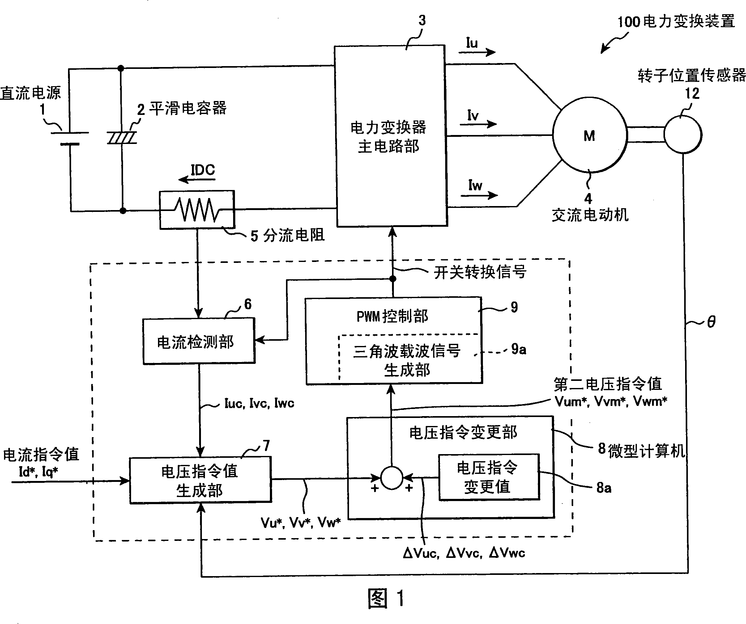
[0030] A first embodiment of the present invention will be described using the configuration diagram of FIG. 1 . The power conversion device 100 in FIG. 1 includes a DC power supply 1, a smoothing capacitor 2 connected in parallel, and a power converter main circuit section (power converter circuit section) that applies a voltage across the smoothing capacitor 2 to the input side through a shunt resistor 5. 3. An AC motor 4 connected to the AC output of the power converter 3, a rotor position sensor 12 installed on the AC motor 4 and outputting a rotor angle signal θ, and a microcomputer 8.

[0031] The microcomputer 8 has the following functions: the current detection unit 6 inputs the DC bus current IDC flowing in the shunt resistor 5, and reproduces the phase currents Iuc, Ivc, and Iwc; the voltage command value generation unit 7 inputs the reproduced phase currents Iuc, Ivc , Iwc and any externally applied current command value Id * ,Iq * , output the first voltage comma...

no. 2 approach

[0089] A second embodiment of the present invention will be described using the configuration diagram of FIG. 5 . In FIG. 5 , the power conversion device 110 is the configuration of the power conversion device 100 according to the first embodiment, with the rotor position sensor 12 deleted, and a rotor position estimation calculation unit 10 for estimating the rotor position of the AC motor 4 is added instead of the rotor position sensor. .

[0090] The rotor position estimation calculation unit 10 receives the reproduced currents Iuc, Ivc, and Iwc obtained by reproducing the motor currents Iu, Iv, and Iw as input, performs estimation calculation of the rotor position, and outputs a phase signal θc of the estimated rotor position. The rotor position estimation calculation uses the first voltage command value Vu * 、Vv * 、Vw * , internal resistance and inductance of the AC motor 4 and other motor constant values ​​for calculation. The voltage command generation unit 7 acquir...

no. 3 approach

[0092] A third embodiment of the present invention will be described using the configuration diagram of FIG. 6 . In FIG. 6 , a power conversion device 120 constitutes a speed control system by adding a speed control unit 11 to the configuration of the power conversion device 110 of the second embodiment. The speed control unit 11 uses the output of the rotor position estimation operation unit 10, that is, the speed estimated value ωc and the arbitrarily applied speed command value ω1 * As input, output the d-axis current command value Id * and the q-axis current command value Iq * . The estimated speed value ωc is a differential value of the phase signal θc of the estimated rotor position calculated by the rotor position estimated calculation unit 10 . The speed control unit 11 compares the speed command value ω1 * and the estimated speed value ωc, thereby performing speed control.

[0093] In addition, in the case of configuring a speed control system, the rotor angle si...


PUM


Abstract

The present invention provides a power conversion device, comprising: a PWM control unit (9), which compares a three-phase AC signal (Vum*, Vvm*, Vwm*) with a triangular wave carrier signal to generate a pulse width modulated wave; a power converter the main circuit part (3), which drives the switching element according to the pulse width modulation wave, and converts the DC voltage into a three-phase AC voltage; and the current detection part (5, 6), which is in the main circuit part of the power converter The DC input side detects the DC bus current to reproduce the phase current; the power conversion device also includes a voltage command change part (8), which uses an odd number of units of 3 or more as the voltage command change period, and the unit period is a triangular wave carrier signal monotonous During the period of increase or monotonous decrease, a correction signal whose average value of the correction amount in the voltage command change period is zero or approximately zero is added to the three-phase AC signal. As a result, the DC bus current is detected with high precision, and harmonic components are suppressed.

Description

technical field [0001] The present invention relates to a power conversion device that detects a DC bus current to obtain current information on an AC side. Background technique [0002] In a power conversion device such as an inverter or a converter, the function of DC-AC conversion or AC-DC conversion is realized by pulse width modulation (hereinafter referred to as "PWM"). Inverters are used in driving systems of AC motors (hereinafter referred to as "motors") such as synchronous motors and induction motors, and converters are widely used as power supply devices such as inverters. [0003] When the motor is driven by the inverter, in order to control the torque generated by the motor with high precision, it is necessary to extract only the fundamental wave component contained in the alternating current with high precision. In general, high-frequency pulsation components caused by PWM are superimposed on alternating currents, so only the fundamental wave components are ex...

Claims


Application Information

Patent Timeline
Patent Type & Authority Applications(China)
IPC IPC(8): H02M7/48H02P27/08
CPCH02M7/53871H02M7/5395H02M1/0009
Inventor 青柳滋久岩路善尚坂本洁户张和明
Owner HITACHI POWER SEMICON DEVICE
Why Eureka
Try Eureka