Primitive cell scattered type electro-magnetic forbidden band structure

An electromagnetic band gap, discrete technology, applied in the field of materials, can solve the problems of reducing the number of unit cells, the size of the unit cell is too large, affecting the suppression of electromagnetic wave propagation, etc., to achieve the effect of improving the performance of the device

Inactive Publication Date: 2008-06-04
SHANGHAI FANGSHENG INFORMATION TECH
View PDF0 Cites 2 Cited by
  • Summary
  • Abstract
  • Description
  • Claims
  • Application Information

AI Technical Summary

Problems solved by technology

[0004] The purpose of the present invention is to provide a kind of original cell discrete electromagnetic bandgap structure, the electromagnetic bandgap structure of this original cell discrete type will solve the single cell size of the electromagnetic bandgap structure in the prior art caused by too large The reduction of the number of cells affects the technical problem of suppressing the propagation of electromagnetic waves

Method used


Image

  • Primitive cell scattered type electro-magnetic forbidden band structure
  • Primitive cell scattered type electro-magnetic forbidden band structure
  • Primitive cell scattered type electro-magnetic forbidden band structure

Examples


Embodiment Construction

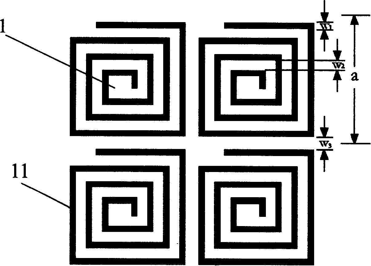
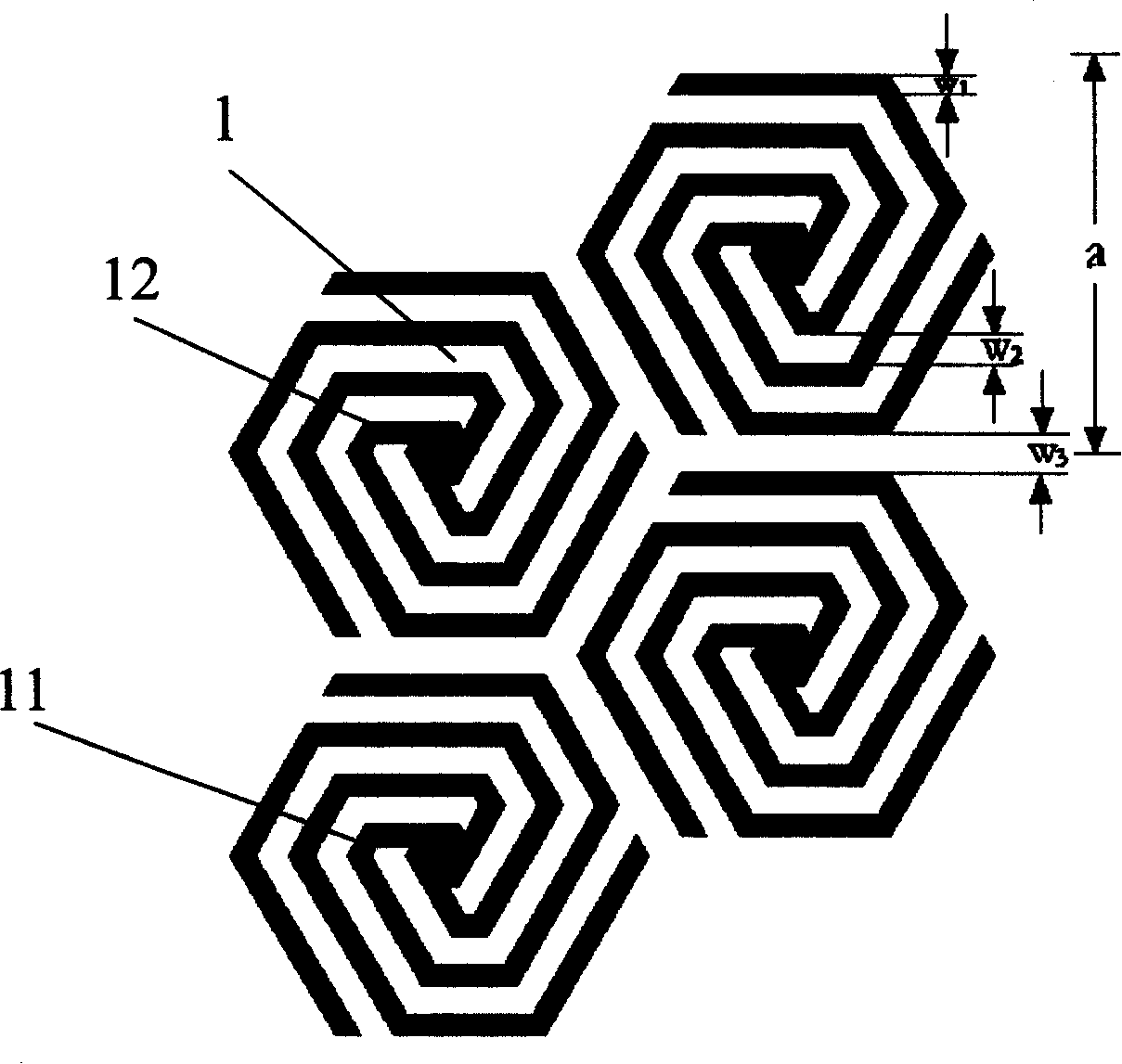
[0019] Such as figure 1 and image 3 As shown, the original cell discrete electromagnetic bandgap structure of the present invention is composed of a parasitic element array, a ground plane and a dielectric layer, and the dielectric layer is arranged between the parasitic element array and the ground plane, and the parasitic The element array includes a planar photonic crystal array, the parasitic element array and the grounding plate are made of conductive materials, and the dielectric layer is made of insulating materials. It is characterized in that the planar photonic crystal is a planar spiral photonic crystal, and the The periodic cell of the above-mentioned planar spiral photonic crystal is formed by a helix 1, and the helixes between adjacent cells are not connected. At this time, each spiral metal wire 11 is wound symmetrically, and each spiral metal wire 11 is connected to the center 12 of the original cell, or may not be connected to each other at the center, and t...


PUM


Abstract

The invention discloses an electromagnetic forbidden zone structure with an original cell discrete type, which comprises a parasitic element array, an earth plate, and a dielectric layer. The dielectric layer is arranged between the parasitic element array and the earth plate; the parasitic element array includes a plane photon crystal array; a plane photon crystal is a plane spiral photon crystal; a cycle original cell of the plane spiral photon crystal is intertwined by a helix; the helixes of the neighboring original cell are mutually isolated; the helix comprises more than one spiral wire and each spiral wire is intertwined symmetrically; the original cells of the plane spiral photon crystal present such shapes as a square, an equilateral triangle, a regular hexagon, etc. The pattern size of the cycle original cell provided by the invention is determined by an applied frequency scope. A linear relationship is formed when same substrate material is used and an accurate design can be made based on the current theory.

Description

Technical field: [0001] The invention relates to the field of materials, in particular to a bandgap material applied in the electromagnetic field, in particular to a discrete electromagnetic bandgap structure. Background technique: [0002] Electromagnetic bandgap structures or photonic bandgap materials have broad application prospects in the field of microwave and optical communications due to their unique characteristics of suppressing the propagation of electromagnetic waves in a certain frequency band, and have aroused widespread interest in recent years. According to the different arrangements of periodic structures, they can be divided into four categories: three-dimensional, two-dimensional, one-dimensional and planar. Among them, the planar or quasi-planar structure has become the most researched aspect because of its low profile and simple preparation process. [0003] In the prior art, typical planar or quasi-planar electromagnetic bandgap structures include the ...

Claims


Application Information

Patent Timeline
IPC IPC(8): H01P1/20H05K9/00G12B17/02
CPCH01P1/2005
Inventor 胡丹红王昕关放傅荣堂资剑刘晓晗
Owner SHANGHAI FANGSHENG INFORMATION TECH
Why Eureka
Try Eureka