Gantry type ultra-precise fly miller

An ultra-precision, gantry-type technology, applied in the field of milling machines, can solve problems such as failure to provide, and achieve the effects of easy operation, symmetrical structure, and high precision

Inactive Publication Date: 2008-06-11
HARBIN INST OF TECH
View PDF0 Cites 19 Cited by
  • Summary
  • Abstract
  • Description
  • Claims
  • Application Information

AI Technical Summary

Problems solved by technology

[0003] In order to solve the problem in the prior art that there is no special equipment for planar ultra-precision machining to process functional materials such as KDP crystals u

Method used


Image

  • Gantry type ultra-precise fly miller
  • Gantry type ultra-precise fly miller
  • Gantry type ultra-precise fly miller

Examples


specific Embodiment approach 1

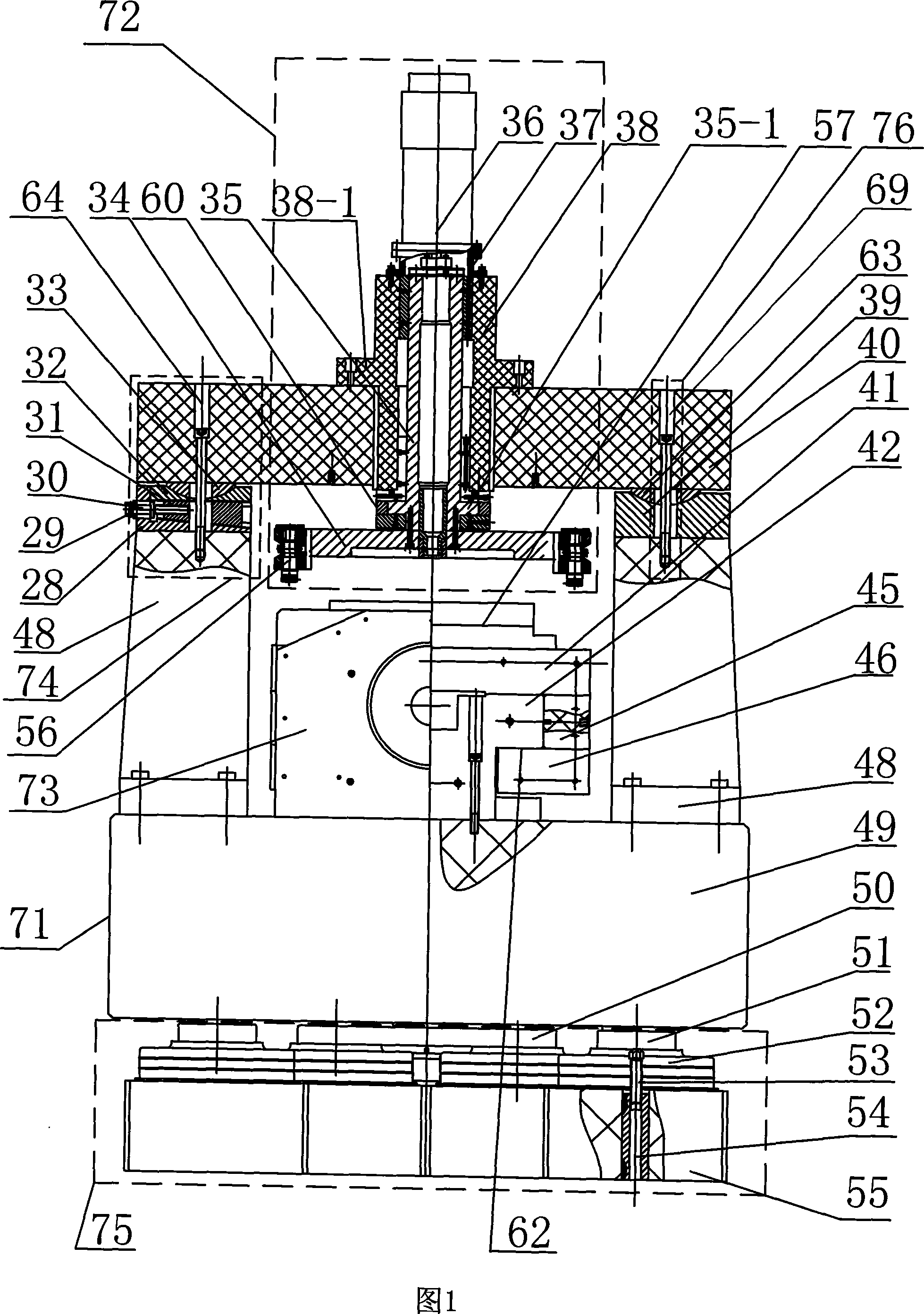
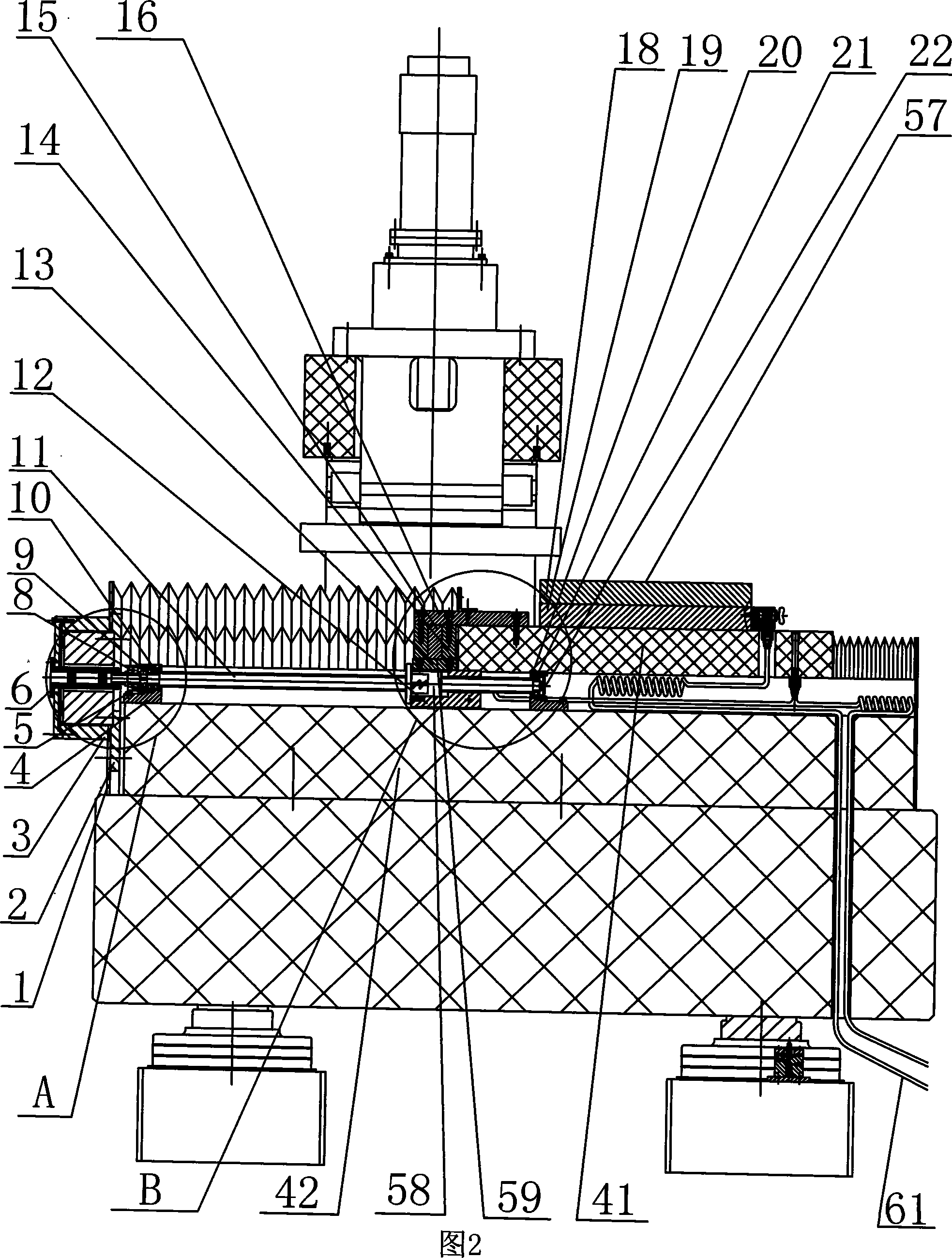
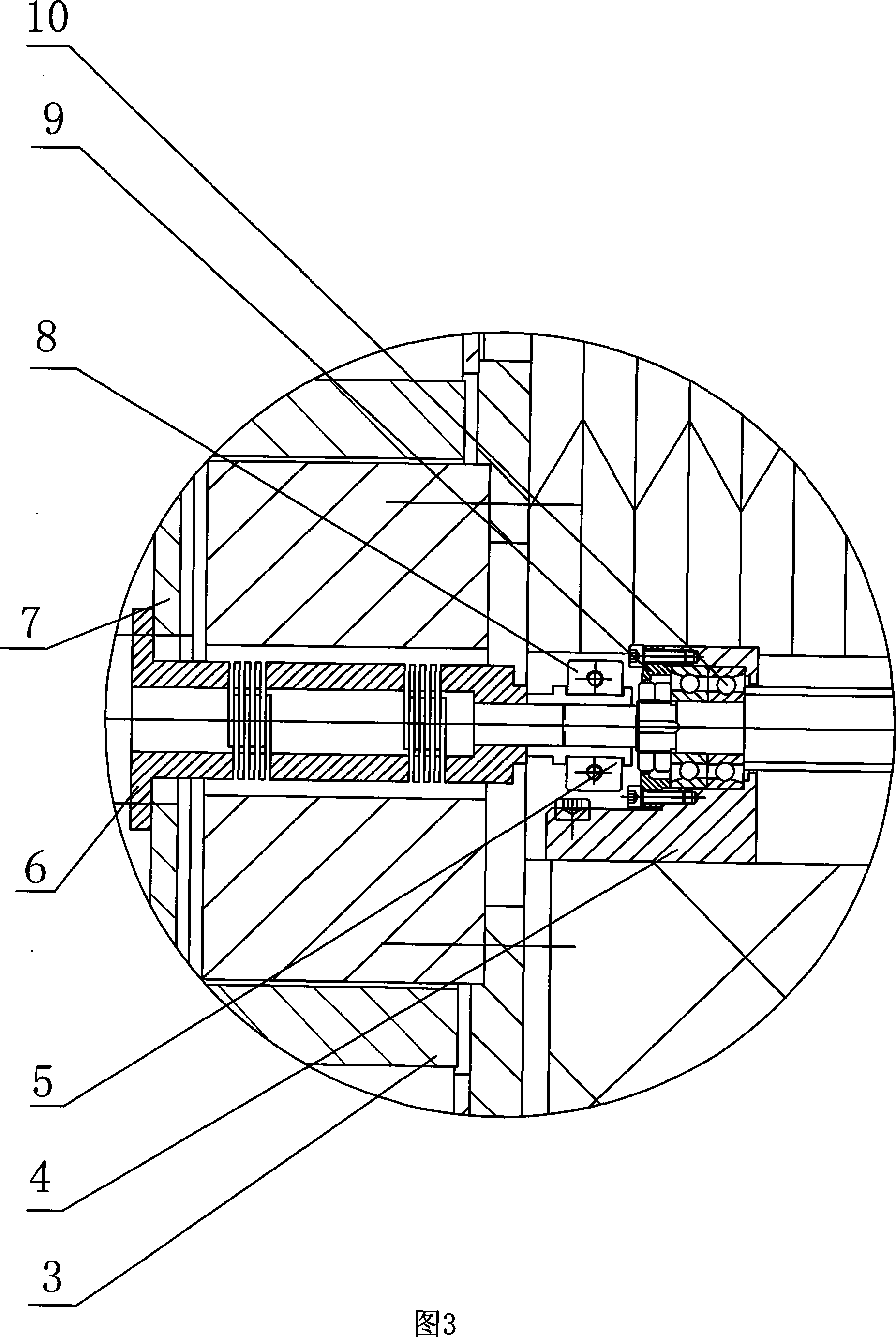
[0007] Specific embodiment one: as shown in Figures 1 to 4, the gantry-type ultra-precision fly-cutting milling machine of this embodiment is composed of a gantry-type bed 71, a spindle system 72, a linear guide rail system 73, and a high-pressure gas pipeline device 61; The gantry bed 71 is composed of a crossbeam 40, two columns 48, and a base 49. The spindle system 72 is composed of a spindle motor 36, a gas static pressure spindle 35, a spindle sleeve 38, a gas static pressure bearing 60, and a flying cutter head. 34. The tool assembly 56 is composed of the linear guide rail system 73 consisting of a guide rail 42, an upper slide 41, two lower slides 46, two intermediate slides 45, a vacuum sucker 57, a motor 3, a flexible coupling 6, Lead screw 11, screw nut 58, gas static pressure coupling 59, screw seat 4, screw back seat 20, screw bearing 10, rear bearing 21, screw nut air bearing seat 12, and locking device 8 are composed; The two columns 48 are located on the left an...

specific Embodiment approach 2

[0011] Embodiment 2: As shown in FIGS. 1-4 , the vacuum chuck 57 in this embodiment is composed of an upper suction cup 18 and a lower suction cup 19 . Such a design facilitates the processing of air holes in the vacuum suction cup. Other compositions and connections are the same as in the first embodiment.

specific Embodiment approach 3

[0012] Specific embodiment three: As shown in Figures 1 to 4, the gas static pressure coupling 59 in this embodiment is composed of an air-floating push plate seat 13, an air-floating push plate 15, two air-floating thrust plates 14, an air-floating push plate Thrust plate bearing 16 is formed, and described air-floating thrust plate seat 13 is fixedly connected with the lower end of air-floating pushing plate 15, and two air-floating thrusting plates 14 are positioned at the both side end surfaces of air-floating pushing plate 15, two air-floating pushing plate 15 The upper end of the floating thrust plate 14 is fixedly connected with the air-floating thrust plate support 16 . Such a design facilitates processing and improves movement precision. Other compositions and connections are the same as in the first embodiment.


PUM


Abstract

The invention discloses a gantry type ultra-precise fly-cutting milling machine and relates to a milling machine. The invention solves functional and material problems that special equipment which is used to manufacture surfaces ultra-precisely can't be provided in the prior art to manufacture KDP crystals which are needed urgently in the non-leaner optical field and the like. A main shaft sleeve (38) is sleeved on an aerostatic main shaft (35), a flying cutter plate (34) is installed on the lower end of the aerostatic main shaft (35), two ends of an upper sliding plate (41) are respectively connected fixedly with two lower sliding plates (46) through two middle sliding plates (45) and formed into a groove (62), the upper end of a guiding rail (42) is installed in the groove (62), a vacuum chuck (57) is installed on the upper sliding plate (41), a screw nut (58) is sleeved on a screw lead (11), and two ends of the screw lead (11) are installed on the guiding rail (42). Linear feeding movements with high precision and rotary movements of a flying cutter can be realized by the invention, both the guiding rail and the main shaft adopt a controlling mode of aerostatics, and the invention has the advantages of high precision and non-pollutions.

Description

technical field [0001] The present invention relates to a milling machine. Background technique [0002] With the continuous development of modern high-tech, a large number of functional materials have appeared, such as KDP crystals, which are key components used in high-power solid-state lasers. Due to their special functions and material properties, their processing can only be In order to obtain an ultra-smooth surface, in order to obtain an ultra-smooth surface, in addition to the research on cutting tools and ultra-precision machining technology, ultra-precision machining equipment must be carefully studied by using the ultra-precision flying cutter milling process. In actual work, the processing accuracy and surface quality requirements of some functional materials are very high. For KDP crystals, the geometric size is often required to be 320mm×320mm×10mm; the surface shape accuracy is 0.125μm; the surface roughness is less than 5nm ( RMS); double-sided surface paral...

Claims


Application Information

Patent Timeline
IPC IPC(8): B23C1/00B23Q1/01B23Q5/04B23Q1/25B23Q11/00
Inventor 梁迎春张飞虎张龙江张景和许乔
Owner HARBIN INST OF TECH
Why Eureka
Try Eureka