Piezoelectric resonator and manufacturing method thereof

A piezoelectric vibrator and a manufacturing method technology, which are applied in the manufacture/assembly of piezoelectric/electrostrictive devices, piezoelectric devices/electrostrictive devices, circuits, etc., can solve the problem of inability to obtain performance, reduced productivity, and unsuitability for industrial use. And other issues

Inactive Publication Date: 2008-06-11
SEIKO EPSON CORP
View PDF9 Cites 19 Cited by
  • Summary
  • Abstract
  • Description
  • Claims
  • Application Information

AI Technical Summary

Problems solved by technology

In addition, excessive heating during bonding of the substrates may affect the vibration characteristics of the piezoelectric vibrating reed, resulting in failure to obtain desired performance.
[0013] However, in the conventional method of directly bonding the metal films on the bonding surface as described above, since room temperature bonding is performed at a low temperature from room temperature to 180°C or lower or 100°C or lower, in order to ensure the tuning fork shape or thickness cut There is a problem that it takes a long time to obtain the necessary and sufficient airtight bonding strength of the piezoelectric vibrator with variable vibration mode
Therefore, the productivity is lowered, and it is not suitable for industrial application
On the contrary, in the ...

Method used


Image

  • Piezoelectric resonator and manufacturing method thereof
  • Piezoelectric resonator and manufacturing method thereof
  • Piezoelectric resonator and manufacturing method thereof

Examples


Embodiment Construction

[0045] Hereinafter, preferred embodiments of the present invention will be described in detail with reference to the drawings.

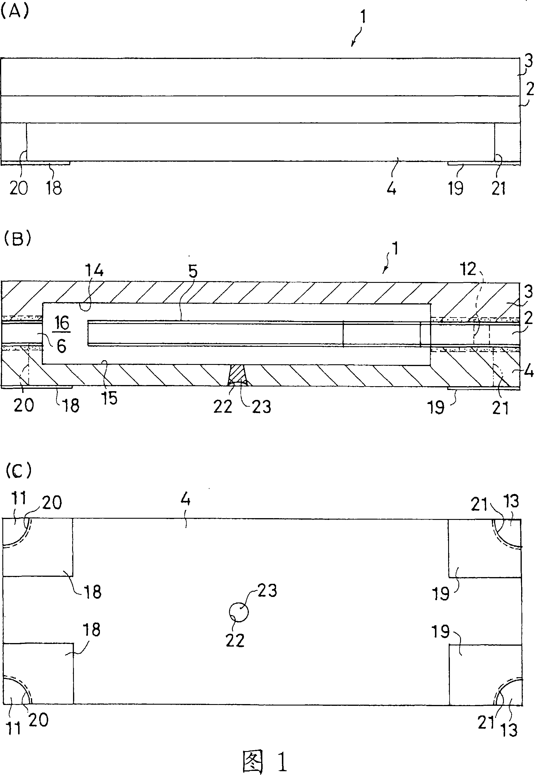
[0046] FIG. 1 shows a first embodiment of a quartz oscillator of the present invention. As shown in FIGS. 1(A) and (B), a quartz resonator 1 has a structure in which an upper substrate 3 and a lower substrate 4 are integrally laminated on the upper surface and the lower surface of an intermediate quartz plate 2 , respectively. The upper substrate 3 and the lower substrate 4 of this embodiment are formed of the same quartz as the intermediate quartz plate 2 . The intermediate quartz plate 2 , the upper substrate 3 and the lower substrate 4 are directly bonded to each other airtightly as will be described later.

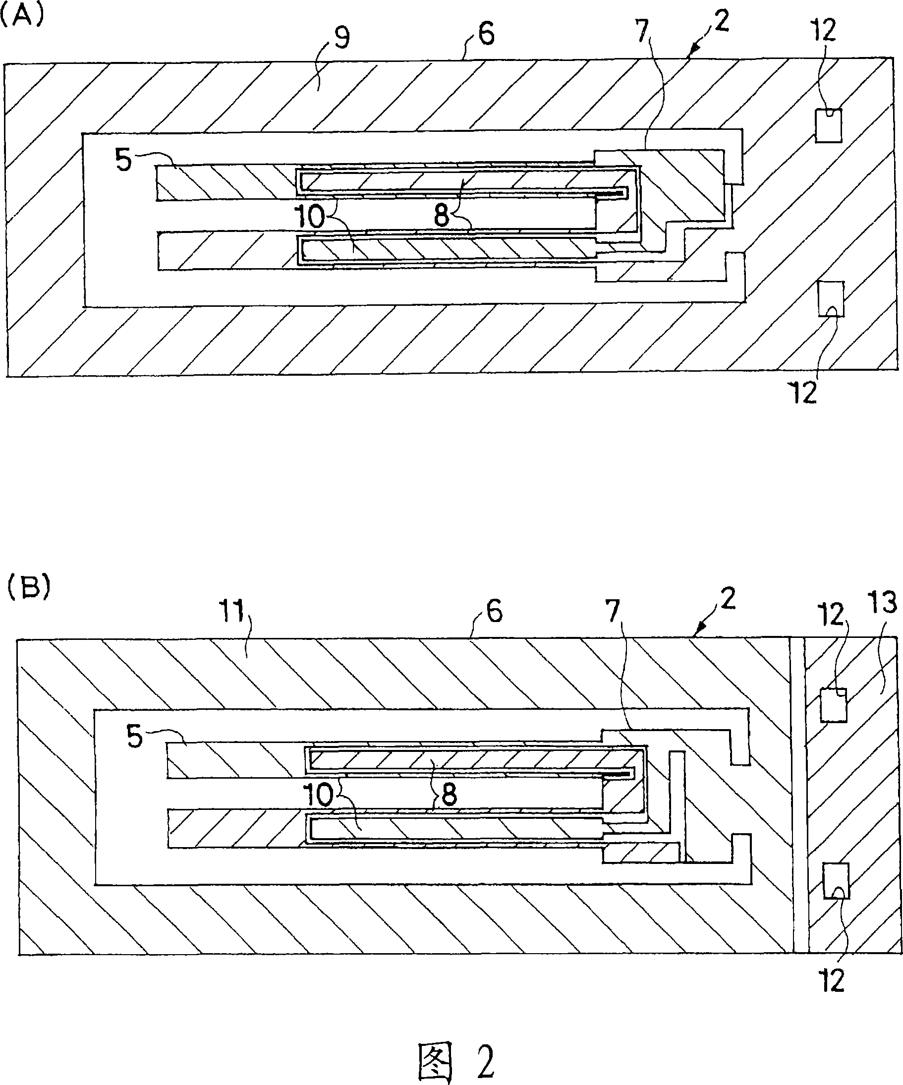
[0047] As shown in FIG. 2(A) and (B), the middle quartz plate 2 integrally forms a tuning-fork-shaped quartz vibrating piece 5 and a housing 6 . The quartz vibrating piece 5 has a pair of vibrating arms extending from the base end portion 7...


PUM


Abstract

The quartz resonator (1 and 51) is provided with a structure which is integrally airtight-connected with upper-side and lower-side substrates (3, 4, 53 and 54) which are overlapped on the upper surface and the lower surface of a middle quartz plate (2 and 52) integrally forming a quartz resonator sheet (5 and 55) and a housing (6 and 56). The upper-side and lower-side substrates are respectively provided with a concave part on a surface facing to the middle quartz plate so as to form cavities (16 and 66) for airtight sealing the quartz resonator sheet in a suspension state. The upper and lower connection surface of the middle quartz plate forms a conductive film (9 and 11) after being grinded and processed at the lens surface. Each connection surface of the upper-side and lower-side substrates consists of bare quartz surfaces which are grinded and processed at the lens surface. In another embodiment, a metal film (67 to 69) is formed on each connection surface of the upper-side and lower-side substrates consists of bare quartz surfaces which are grinded and processed at the lens surface. The upper-side and lower-side substrates and the middle quartz plate are all or one by one overlapped with each other and are then pressurized at room temperature (heated optionally) after whose connection surfaces are surface-activated through plasma processes, so as to be airtight-connected with each other, thereby sealing the cavities in a vacuum or idle gas atmosphere.

Description

technical field [0001] The present invention relates to a piezoelectric vibrator in which a tuning-fork type or a thickness-shear vibration mode piezoelectric vibrating piece is hermetically sealed and packaged, and a method for manufacturing the same. Background technique [0002] With the miniaturization and thinning of electronic equipment, further miniaturization / thinning of piezoelectric devices such as quartz oscillators is required. Conventionally, piezoelectric devices are mostly surface-mounted devices suitable for mounting on circuit boards and the like. Generally, surface-mount piezoelectric devices generally use a structure in which a piezoelectric vibrating reed is sealed in a package made of an insulating material such as ceramics. In the conventional package structure, the substrate and the lid are joined by low-melting-point glass or seam welding. Therefore, due to the influence of the gas generated by the low-melting-point glass and the high heat of the seam...

Claims


Application Information

Patent Timeline
IPC IPC(8): H03H9/215H03H9/19H03H3/02H01L41/09H01L41/22H01L23/02H01L23/06H03H9/02
CPCH03H9/0595H03H3/04H03H9/1035H03H2003/026H03H9/215H03H3/02H10N30/80
Inventor 黑田贵大棚谷英雄
Owner SEIKO EPSON CORP
Why Eureka
Try Eureka