Gas-shielded arc welding method

A gas shielded and arc welding technology, applied in arc welding equipment, welding media, welding equipment, etc., can solve the problems of weld shape deterioration, weld width expansion, poor appearance, etc., improve joint fatigue characteristics, prevent cracks and Good porosity and uniformity

Inactive Publication Date: 2008-06-18
KOBE STEEL LTD
View PDF3 Cites 13 Cited by
  • Summary
  • Abstract
  • Description
  • Claims
  • Application Information

AI Technical Summary

Problems solved by technology

[0010] In the welding wire described in the document No. 61-165294 of JP-A-61-165294, there is also 2 Welding creates spatter problems which in turn lead to poor weld bead shape in the low speed range
In addition, as a method of achieving high speed, the focus is on stabilizing the arc and preventing the occurrence of microscopic pores in the short arc length, and no research has been conducted on how to increase the weld width.
[0011] In the technology described in JP-A-5-305476, since S is contained in the welding wire, the effect of making the weld bead wide and flat can indeed be obtained, but the so-called wide bead refers to its average value after all, not only exists There are problems such as poor uniformity of the weld width, generation of fluctuations, and poor appearance. There is also a problem that the fatigue strength cannot be improved because the peaks of the fluctuations become stress concentration points.
In addition, there is an occasional problem of poor penetration relative to the target position of the weld
[0012] The gas-shielded arc welding method described in Patent Publication No. 63-27120 is a method in which an appropriate amount of nitrogen is added to the shielding gas, but since nitrogen can cause significant embrittlement of carbon steel, there is a risk of embrittlement of carbon steel. In addition, in this welding method, only low-speed welding below 50cm / min has the effect of expanding the width of the weld, so it is not suitable for high-speed welding
[0013] In addition, in the existing gas-shielded arc welding method, problems such as cracks and pores occur due to different welding wire components; Problems with splashing

Method used


Image

  • Gas-shielded arc welding method
  • Gas-shielded arc welding method

Examples


Embodiment Construction

[0036] Hereinafter, embodiments of the present invention will be described in detail.

[0037] The invention relates to a gas-shielded arc welding method for pulse welding by adopting a solid welding wire.

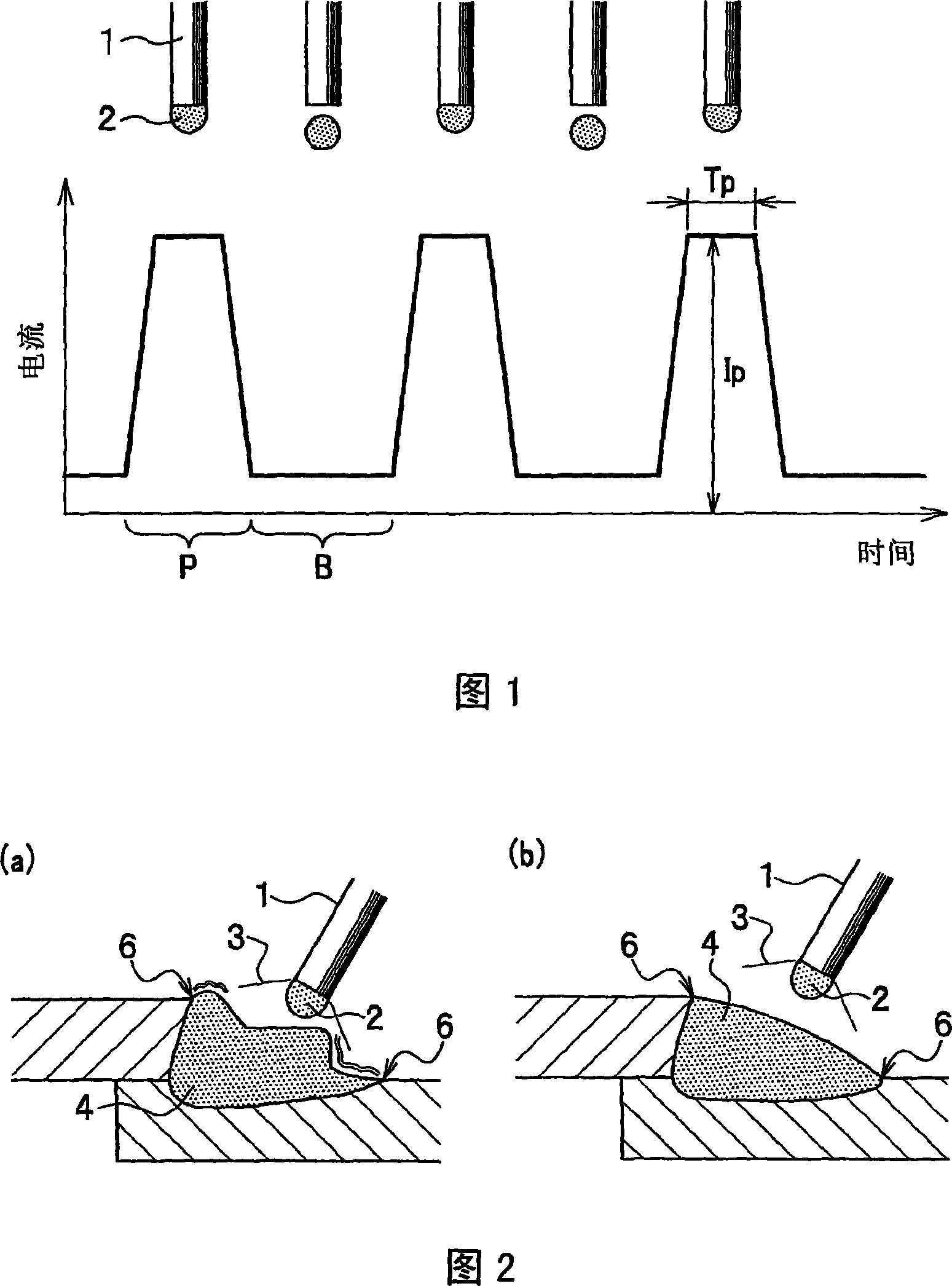
[0038] In addition, the so-called pulse welding here refers to welding performed by pulse-shaped current and voltage waveforms.

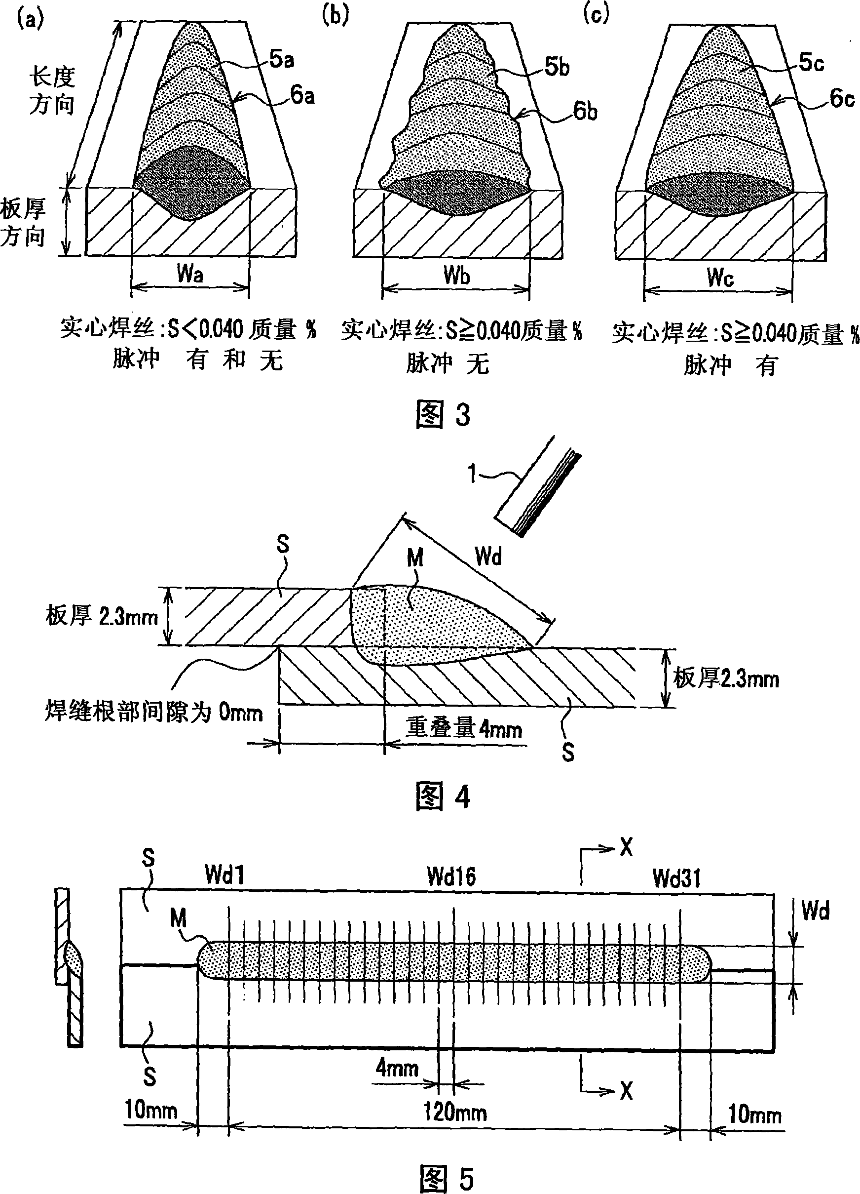
[0039] Moreover, the welding wire contains 0.040 to 0.200% by mass of S, and also contains a predetermined amount of Si, Mn, C, and P, the balance is composed of Fe and inevitable impurities, and the pulse peak current in the pulse of the pulse welding (Ip) is specified to be 350A or more, and the pulse peak period (Tp) is specified to be 0.5 to 2.0 msec. Furthermore, the protective gas used is specified as a prescribed type.

[0040] Hereinafter, each configuration will be described.

[0041] (Solid welding wire)

[0042] In general, the welding wire includes a linear solid welding wire and a flux-cored welding wire filled with flux at the center. ...


PUM


Abstract

A gas-shielded arc welding method uses a shielding gas and a solid wire for pulsation welding. The solid wire contains S, Si, Mn, C and P in predetermined S, Si, Mn, C and P contents, and other elements including Fe and unavoidable elements. A pulsating current used for pulsation welding has a peak current Ip of 350 A or above and a pulse peak duration Tp between 0.5 and 2.0 ms. The shielding gas is a mixed gas containing 75 to 98% by volume Ar and others including at least either of CO2 and O2. The gas-shielded arc welding method can suppress the generation of spatters regardless of welding speed even if the welding speed is high, and can form a wide, flat bead having uniform toes. A weld metal produced by the gas-shielded arc welding method is resistant to cracking and excellent in preventing the formation of blowholes.

Description

Technical field [0001] The invention relates to a gas-shielded arc welding method for pulse welding with a solid wire, in particular to a gas-shielded arc welding method that can be applied in high-speed welding. Background technique [0002] In recent years, in the automotive and other industrial fields, in order to reduce production costs, there has been an increasing demand for higher efficiency of welding processes, especially for higher speeds during welding. However, when high-speed welding is performed, the flow of the molten pool becomes intense, which will result in the deterioration of the uniformity of the weld toe shape; the increase of the arc force causes the weld width to be unable to expand, and the weld shape bulge, that is, the weld seam, appears. Problems such as the convexity of the shape. Especially when the weld shape becomes convex, the allowable range of target deviation (wire target position deviation) relative to the target position of the weld becomes s...

Claims


Application Information

Patent Timeline
Patent Type & Authority Applications(China)
IPC IPC(8): B23K9/16B23K35/30B23K35/38B23K9/09
CPCB23K35/38B23K35/0261B23K35/3053B23K9/09B23K9/173B23K9/16
Inventor 铃木励一梅原悠
Owner KOBE STEEL LTD
Why Eureka
Try Eureka