
Water heat exchange system and method applying alternately solar, fuel oil and gas thermo power

A heat exchange system and a technology for absorbing heat from solar energy, applied in the field of heat exchange devices, can solve the problems of limited heating area of ​​a coil tube, low heat exchange efficiency, limited area for absorbing solar energy, etc. The effect of solar thermal energy and heat exchange is sufficient

Inactive Publication Date: 2008-06-18
李明强
View PDF1 Cites 4 Cited by
  • Summary
  • Abstract
  • Description
  • Claims
  • Application Information

AI Technical Summary

Problems solved by technology

However, the water heat exchange device of this structure also has the following disadvantages: 1. Since the oil and gas burners will produce waste gas during work, and the waste gas usually contains some harmful substances, such as dust, sulfur compounds, etc., waste Emissions will pollute the environment, which is not conducive to the promotion and application of products
2. The air heated by solar energy only performs heat exchange in the water heat exchange device, and the heat of the hot air cannot be completely exchanged. The air discharged from the solar outlet of the water heat exchange device still has a certain amount of heat, and its heat exchange efficiency is low.
3. Its solar heat absorbing device is composed of a snake tube. Since the heating area of ​​the coil tube is limited, the area for absorbing solar energy is also limited, and the solar energy cannot be fully utilized, and the utilization efficiency of the solar energy is low.

Method used


Image

  • Water heat exchange system and method applying alternately solar, fuel oil and gas thermo power
  • Water heat exchange system and method applying alternately solar, fuel oil and gas thermo power
  • Water heat exchange system and method applying alternately solar, fuel oil and gas thermo power

Examples


Embodiment Construction

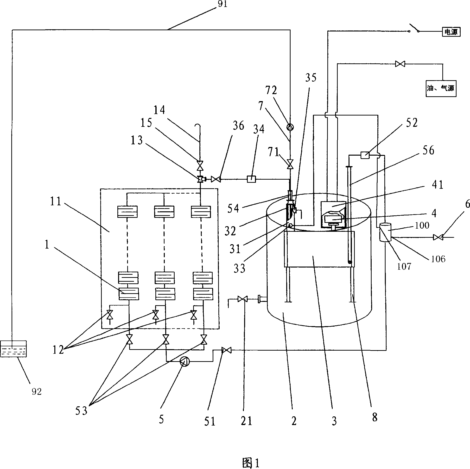
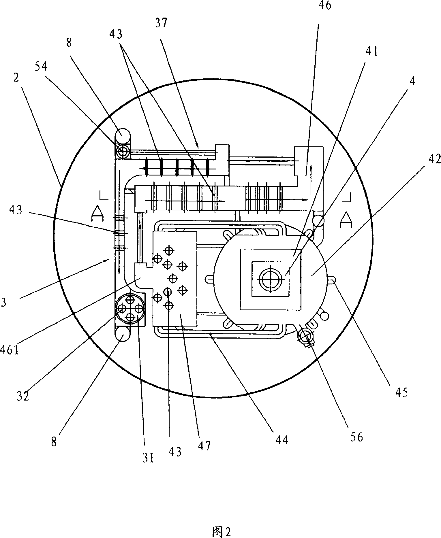
[0039] In order to clearly illustrate the embodiment of the present invention, the legend shown in the figure is now given a general description:

[0040] 1. Solar heat absorbing device;

[0041] 11. Solar heat absorbing device matrix; 12. Matrix sewage valve;

[0042] 13. Solar tube tee; 14. Solar waste heat exhaust pipe;

[0043] 15. Solar waste heat exhaust valve; 16. Upper metal plate;

[0044] 17. Lower metal plate; 18. Surrounding metal plate;

[0045] 19. Windproof board;

[0046] 2. Water storage container;

[0047] 21. Hot water drain valve;

[0048] 3. Water heat exchange device;

[0049] 31. Flue gas waste heat exchange device; 32. Preheating tubes; 33. Connecting water pipe inlet;

[0050] 34. Solar energy inlet heat insulator; 35. Preheating water outlet;

[0051] 36. Solar switch; 37. Solar cooling components;

[0052] 38. Peloton; 39. Solar main pipe;

[0053] 4. Oil and gas burners;

[0054] 41. Water barrier; 42. Combustion chamber; 43. Water pipe;

...


PUM


Abstract

The invention relates to a water heat exchange system and method applied to the exchange of solar energy and fuel, air heat energy. The system comprises a solar heat absorbing device, a fuel / gas burner, a burning chamber, a water heat exchanger and a water tank; the water heat exchanger and the burning chamber are arranged in the water tank; a water-proof tank is arranged on and communicated with the burning chamber; the burner is installed in the waterproof tank; the water heat exchanger is serially connected between the solar heat absorbing device and the burning chamber. The system pre-heats the water which enters into the water tank by setting a solar waste heat device at the solar energy outlet, so as to make full use of the solar energy; dispose the waste gas by a filter connected to a smoke pipe of a flue gas waste heat exchanger, so as to reduce pollution of the waste gas produced by burning of the burner to the air; and the has the advantages of environmental protection and emission reduction. The air flows from bottom to top in flow channels separated by a plurality of air partition boards which are deranged in the box solar heat absorbing device, so that the solar heat energy can be fully absorbed.

Description

technical field [0001] The invention relates to a heat exchanging device, in particular to a water heat exchanging system and method which can use solar heat energy and a burner as a heat source to alternately apply solar energy, fuel oil, and gas heat energy. Background technique [0002] Existing heat exchange devices are generally divided into domestic heat exchange devices, such as showers, or heat exchange devices for bathrooms, such as steam boilers used in factories or bathrooms, in terms of use occasions. In terms of the heat energy used, it is generally divided into solar water heating devices or oil, gas or coal-fired water heating devices. The current solar water heating device generally comprises a solar vacuum heat-absorbing tube and a water storage tank connected thereto. After the solar energy heats the water in the vacuum heat-absorbing tube, it is stored in the water storage tank for subsequent use. This solar heat exchange device, due to its water storage ...

Claims


Application Information

Patent Timeline
IPC IPC(8): F28D1/02F24J2/00F24J2/04F24J2/46
CPCY02E10/44
Inventor 李明强
Owner 李明强
Learn More