
Ultrafast recovery diode

A recovery diode and diode technology, applied in the direction of electrical components, electric solid devices, circuits, etc., can solve the problems of unsuitable structure for high operating frequency, large size of the original packaging form, unsuitable for application needs, etc., to achieve compact structure, reduce Circuit connection, the effect of reducing the temperature rise of the operation

Inactive Publication Date: 2008-06-18
浙江正邦电子股份有限公司
View PDF0 Cites 3 Cited by
  • Summary
  • Abstract
  • Description
  • Claims
  • Application Information

AI Technical Summary

Problems solved by technology

Therefore, in order to be suitable for high-frequency circuits and normal work, fast recovery diodes and chips with fast operating frequencies have been developed. Its common packaging form is also a bolt-type package, so its structure is no longer suitable for new application needs.
Moreover, current fast devices are generally integrated with multiple devices. The application of ultra-fast recovery diodes and chips is usually to form a system with certain functions together with IGBT and other devices. The original package is bulky, which is not conducive to integration. The structure is also not suitable for high operating frequency

Method used


Image

  • Ultrafast recovery diode
  • Ultrafast recovery diode

Examples


Embodiment Construction

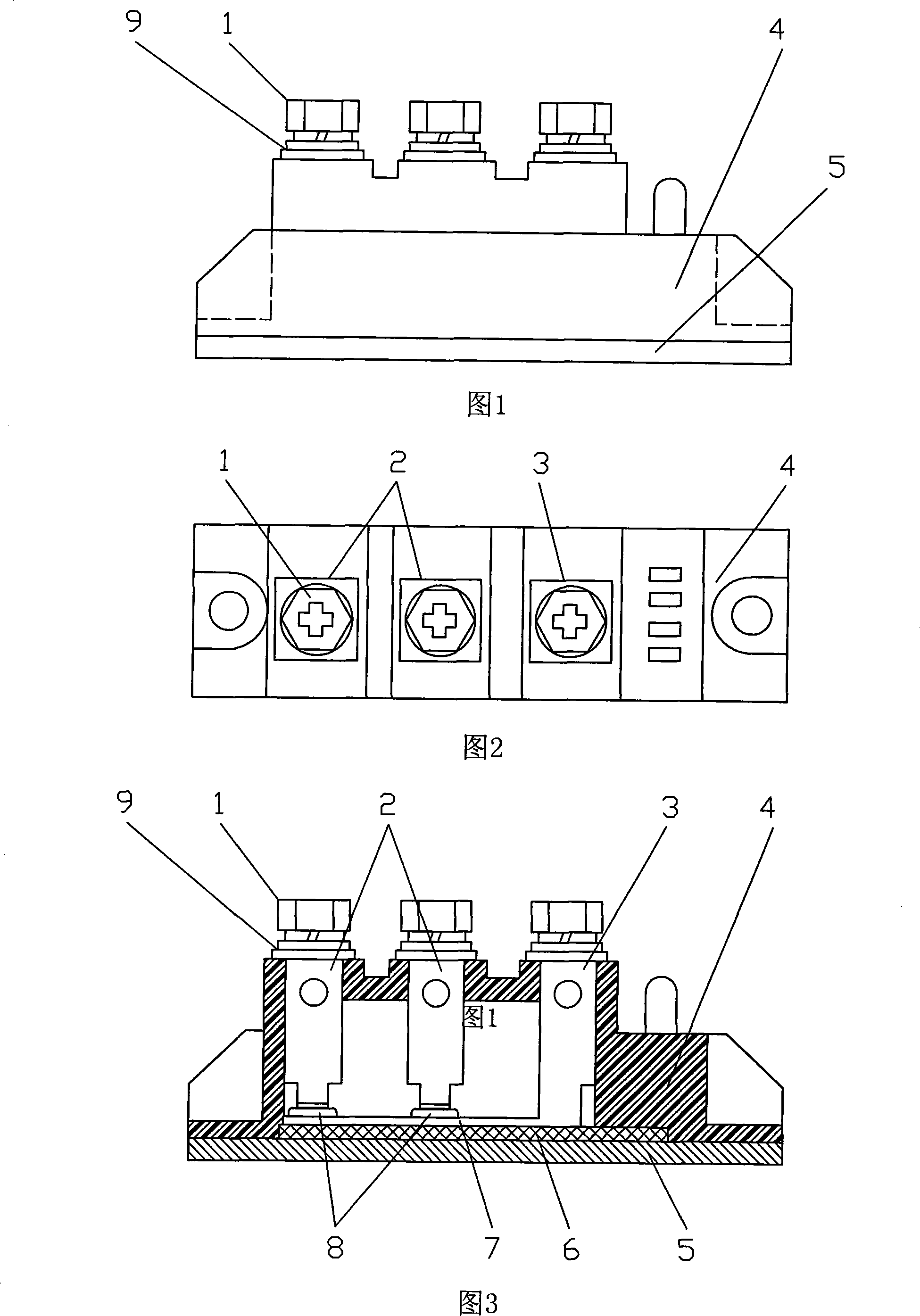
[0017] Referring to Fig. 1, for an ultrafast recovery diode, two diode chips 8 are arranged in the insulating casing 4, and the cathodes of the diode chips 8 are welded on the copper electrode plate 7 and then welded to the beryllium oxide sheet 6 and the copper base plate 5 in turn , the anode is led out by the conductive sheet 2 respectively, and the copper electrode plate 7 is led out by the cathode conductive sheet 3 . The anode of the diode chip 8 and the anode conductive sheet 2 are also fixed by welding. The soldering is lead-tin soldering. Gaskets 9 and nuts 1 are provided on the upper ends of each conductive sheet 2 and 3 for electrical connection with an external circuit.

[0018] It should be understood that: the above-mentioned embodiments are only descriptions of the present invention, rather than limitations of the present invention, and any inventions that do not exceed the spirit of the present invention fall within the protection scope of the present inventio...


PUM


Abstract

The invention discloses an ultra-rapid recovered diode, the insulating shell of which is provided with a diode chip; the invention is characterized in that: the cathode of the diode chip is welded on an insulating plate and a copper bottom plate sequentially after being welded on a copper electrode plate, and the anode thereof is conducted out by a conductive strip; the cooper electrode plate is conducted out by the cathode conductive strip. The ultra-rapid recovered diode of the invention, which adopts the module-type encapsulating structure, has the advantages of freely combining two or more chips by common-cathode connection according to the need of the circuit structure, increasing the working electric flow, ensuring the short time of the reverse-recovery, and facilitating the installation owing to the insulating bottom plate. Meanwhile, the invention has compact structure, can reduce circuit connection and improve operation security, and the copper bottom plate can be both a heat conduction component and a heat dissipation component, which can lower working temperature-rising, and increase working electric flow.

Description

technical field [0001] The invention relates to the field of power electronic devices, in particular to an ultrafast recovery diode, which is mainly used in medium and high frequency electronic circuits. Background technique [0002] Power electronics technology is a marginal technology between automatic control technology, electronic technology and electric power technology. Since the birth of power electronic devices, it has developed very rapidly and is applied to all aspects of power generation, conversion and use. All fields of the national economy show their talents. It has the characteristics of wide application, convenient control, high efficiency and energy saving, and is listed as one of the key technologies for key development by various countries. Power electronic devices are the foundation and key of power electronics technology, and the emergence of each new power electronic device has brought about a revolutionary development of power electronics technology. ...

Claims


Application Information

Patent Timeline
Patent Type & Authority Applications(China)
IPC IPC(8): H01L29/861H01L23/48H01L23/08
CPCH01L2924/0002
Inventor 周伟庆项卫光徐伟
Owner 浙江正邦电子股份有限公司
Learn More