Large volume sample injection method and special chip in micro-current-control chip

A microfluidic chip, large-volume sample injection technology, which is applied in measurement devices, instruments, scientific instruments, etc., can solve the problems of high channel size requirements on the microfluidic chip, poor separation effect, and difficulty in automation. Create fast, easy to automate, and achieve automated effects

Inactive Publication Date: 2008-06-25
DALIAN INST OF CHEM PHYSICS CHINESE ACAD OF SCI
View PDF0 Cites 8 Cited by
  • Summary
  • Abstract
  • Description
  • Claims
  • Application Information

AI Technical Summary

Problems solved by technology

[0005] However, the commonly used microfluidic chip chromatographic enrichment method needs to replace the solution many times, the operation is cumbersome, it is not easy to realize automation, and the size of the channel on the microfluidic chip is relatively high.
If the solution transport channel before the separation channel is oversized, it is easy to introduce dead volume
It not only makes the separation effect worse and the reproducibility is reduced, but also causes the gradient delay effect in the gradient separation

Method used


Image

  • Large volume sample injection method and special chip in micro-current-control chip
  • Large volume sample injection method and special chip in micro-current-control chip
  • Large volume sample injection method and special chip in micro-current-control chip

Examples


Embodiment 1

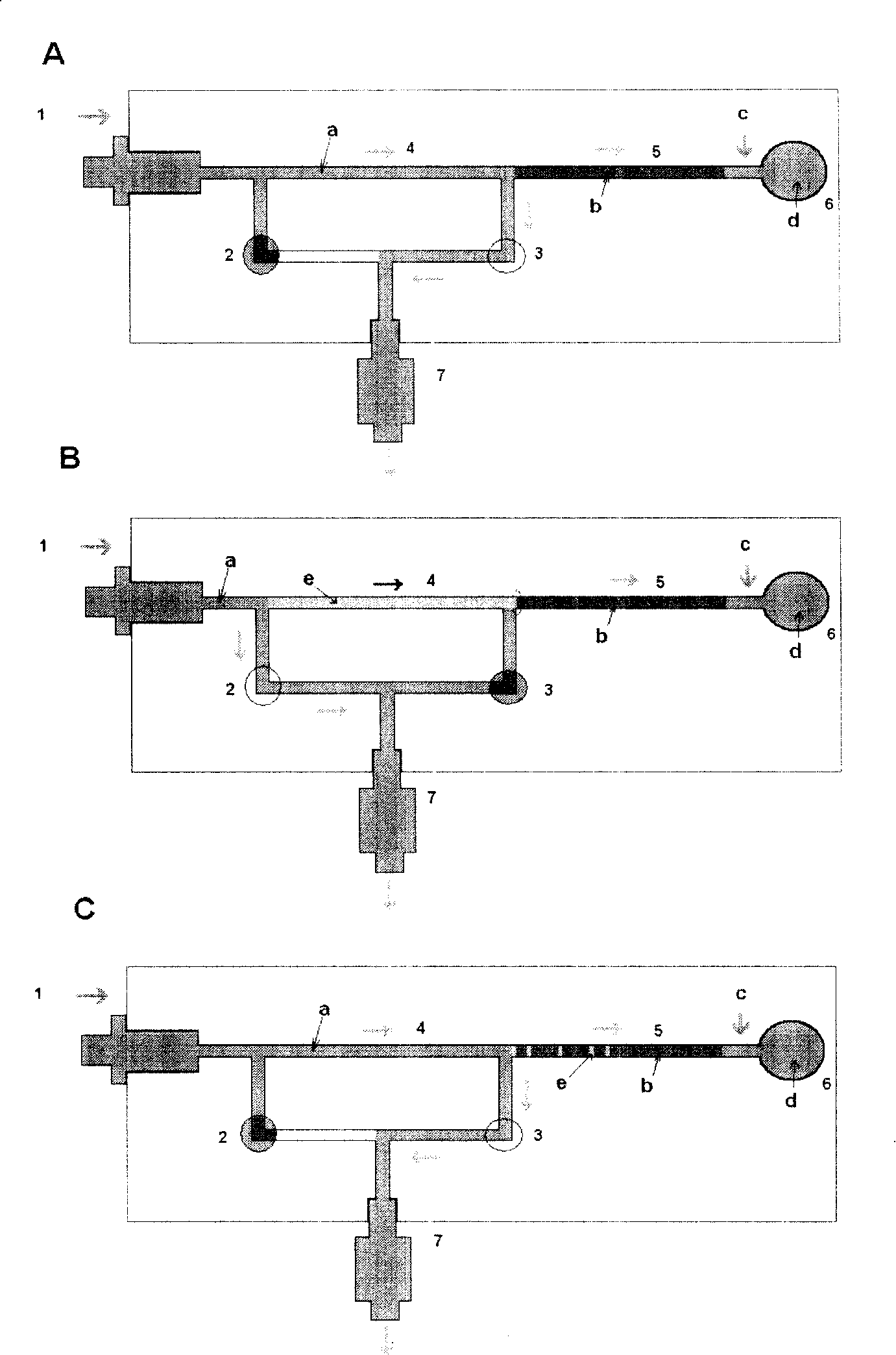
[0021] see figure 1 , the present invention provides a device for large-volume sampling in a microfluidic chip, which consists of a pump interface 1, a flow controller 2, a flow controller 3, a sampling channel 4, a separation channel (including stationary phase b) 5, The waste liquid tank 6 and the pressure controller 7 are composed. Sample e can be separated by pressure-driven or electric-driven, in which flow path controllers 2 and 3 are temperature flow path cut-off controllers.

[0022] When equilibrating the stationary phase b in the separation channel, as figure 1 -A, close the flow controller 2, and open the flow controller 3. The mobile phase a passes through the injection channel 4 at a high flow rate, and is split before the separation channel 5 . The pressure in the device is controlled by a pressure controller 7 .

[0023] During sample injection, such as figure 1 -B, sample e can be introduced into the flow path by the injection valve, and then transported i...

Embodiment 2

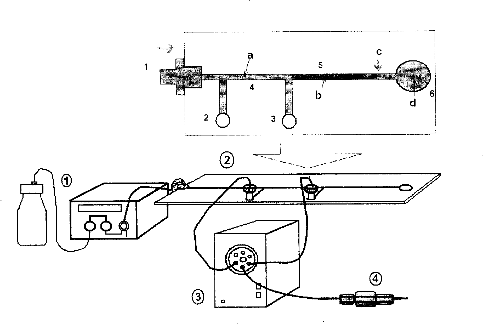
[0026] Such as figure 2 As shown, the microfluidic chip uses an external flow switching system to switch the flow path, and the purpose of large-volume sample injection can still be achieved. Among them, ① is a pump and a sampling device; ② is a microfluidic chip; ③ is a switching device; ④ is a pressure control device. The microfluidic chip includes an interface 1 with the pump, interfaces 2 and 3 connected with an external flow switching system, a sampling channel 4 , a separation channel (including stationary phase b) 5 and a waste liquid tank 6 .

[0027] When balancing the stationary phase b in the separation channel, the flow path 2 is closed and the flow path 3 is opened through an external flow path switching system. The mobile phase a passes through the injection channel 4 at a high flow rate, and is split before the separation channel 5 . The pressure in the device is controlled by an external pressure controller d.

[0028] When the sample is injected, the sampl...

Embodiment 3

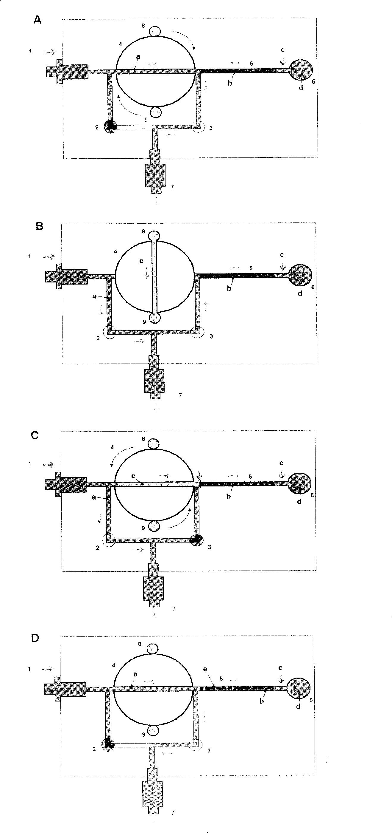
[0031] Such as image 3 As shown, the present invention provides a microfluidic chip large-volume sampling device with a rotary sampling valve, consisting of a pump interface 1, a flow controller 2, a flow controller 3, a rotary sampling valve 4, and a separation channel ( It consists of stationary phase b) 5, waste liquid tank 6, pressure controller 7, sample injection tank 8 and sample waste liquid tank 9. The sample can be introduced into the microfluidic chip by pressure or electric drive, and the sample can be separated by pressure drive or electric drive. Wherein the flow path controller is a temperature flow path cut-off controller.

[0032] When equilibrating the stationary phase b in the separation channel, as image 3 -A, close the flow controller 2, and open the flow controller 3. The mobile phase a passes through the sample channel of the rotary sampling valve 4 at a high flow rate, and is divided before the separation channel 5 . The pressure in the device is ...


PUM


Abstract

The invention relates to a sample injection method of a micro fluidic chip system, in particular to a large-volume sample injection method and a special chip adopted in a micro fluidic chip, wherein, two or more than two shunt channels are arranged between a chip separation channel and a mobile phase inlet inside a micro fluidic chip system adopting fixed stationary phase; large-volume sample injection of the micro fluidic chip system is realized through controlling the switching and cutoff of the fluid inside the system. The method is suitable for large-volume sample injection inside a micro fluidic chip in electrochromatography mode, compression electrochromatography mode and liquid phase chromatogram. Moreover, the method has the advantages that: sample injection of large-volume sample inside a micro fluidic chip can be realized; the invention overcomes the gradient delay effect of the system, and is particularly suitable for gradient separation; moreover, the invention has the characteristics of simple strucuture, convenient operation, small dead volume, small pre-column effect and good sample injection repeatability, etc.

Description

technical field [0001] The invention relates to a sampling method for a microfluidic chip system, in particular to a large-volume sampling method in a microfluidic chip and a dedicated chip. Background technique [0002] The concept of Miniaturized Total Analysis System (μTAS) was first proposed in the 1990s. In the following ten years, this field has developed into one of the most cutting-edge scientific and technological fields in the world today, and its core technology is the microfluidic chip. [0003] Microfluidic chips have the advantages of small size, easy integration, automation, fast analysis speed, high separation efficiency, and significantly reduced consumption of reagents and samples. However, since the injection volume of microfluidic chips is usually from picoliters to nanoliters, this requires a very high sensitivity of the detector. This limits the application of microfluidic chips to a certain extent. [0004] One of the effective ways to solve this pr...

Claims


Application Information

Patent Timeline
Patent Type & Authority Applications(China)
IPC IPC(8): G01N35/00G01N30/16
Inventor 张丽华段继诚丛永正王晖张维冰梁作成张玉奎
Owner DALIAN INST OF CHEM PHYSICS CHINESE ACAD OF SCI
Why Eureka
Try Eureka