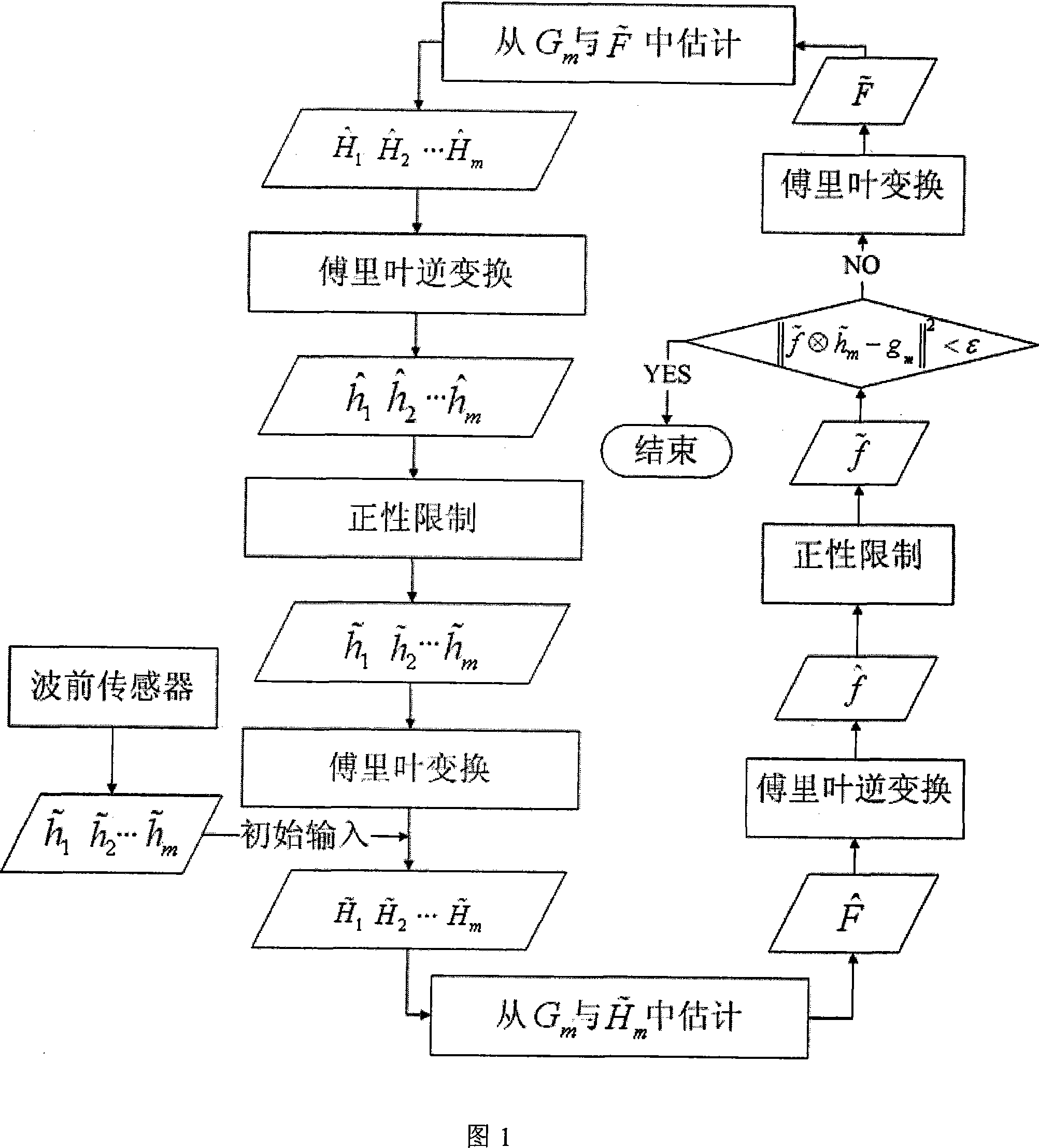
Multi-frame self-adaption optical image high resolution restoration method using wave front data
A technology of adaptive optics and wavefront data, applied in the field of image processing, can solve problems such as poor adaptability and unguaranteed convergence, and achieve the effects of enhancing robustness, easy convergence, and improving restoration quality
- Summary
- Abstract
- Description
- Claims
- Application Information
AI Technical Summary
Problems solved by technology
Method used
Image

Examples
Embodiment 1
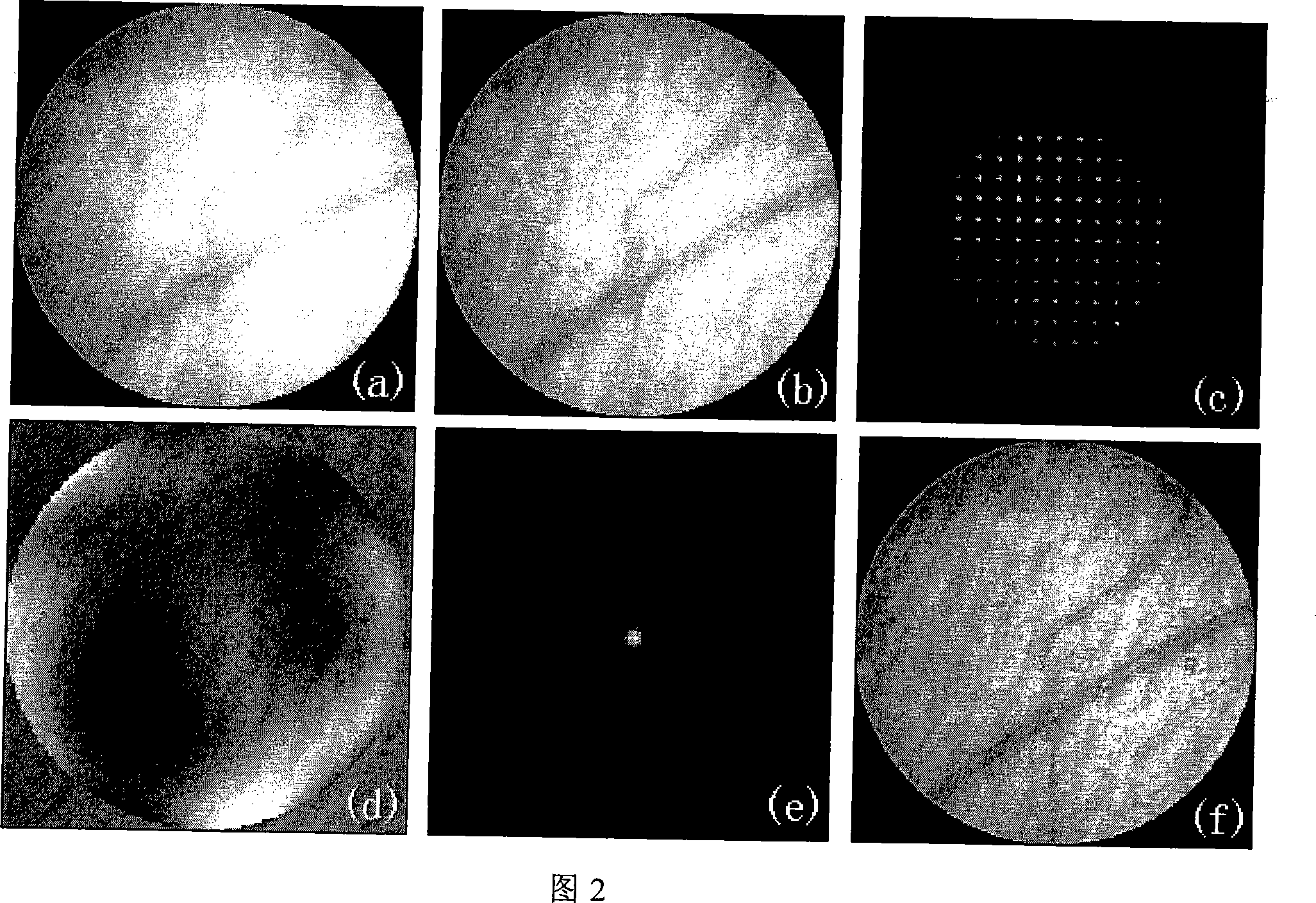
[0044] As shown in Figure 2, the human eye image of the present invention is used for restoration. (a) is a degraded image of 100 pixels×100 pixels that has not been corrected by the adaptive optics system, (b) is the image after adaptive optics correction, and (c) is the residual error recorded by the corrected wavefront sensor For the slope data, (d) is the wavefront aberration restored from (c), (e) is the point spread function corresponding to the wavefront aberration, and (f) is the image restored by the present invention. It can be seen from the experimental results that the quality of the restored image is greatly improved compared to (a) and (b), reflecting more details. The entire calculation process went through 25 iterations and took 20 seconds.
Embodiment 2
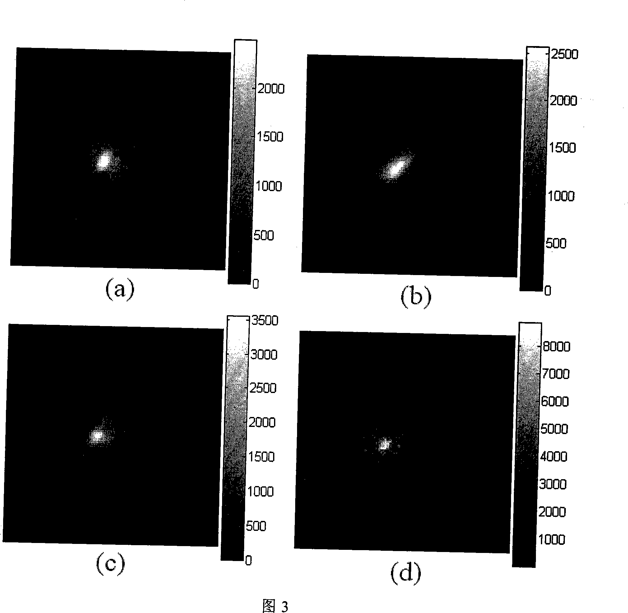
[0046] The application of the present invention is used to restore the partially corrected image of the adaptive optical system, as shown in FIG. 3. (a)~(c) are three frames of 100 pixels×100 pixels stellar target after adaptive optical correction. (d) is the result of secondary correction by the method of the present invention. Experiments show that the restoration results are better. It can be seen from Figure 3 that under the same energy, the peak value of (d) is 2.56 times, 2.47 and 1.49 times higher than that of (a) ~ (c), which means that the Strehl ratio is increased by 2.56 times. , 2.47 and 1.49 times. Figure 4 compares the cross-sectional views of Figure 3 (a) and (d). It can be further found from Figure 4 that after the second correction, the FWHM of Figure 3(d) is increased by nearly 4 pixels compared to Figure 3(a), reaching 5.9 pixels, which is close to the diffraction limit of the entire optical system of 4.8 pixels. The entire restoration process converges after 25...
Embodiment 3
[0048] As shown in Figure 5, (a) to (c) are also three frames of 100 pixels×100 pixels stellar targets after adaptive optical correction, but the system correction quality is improved compared to Example 1. (d) is the result of secondary correction by the method of the present invention. The experimental results also show that the restoration results are better. The Strehl of (d) is also greatly improved compared to (a) to (c). Figure 6 compares the cross-sectional views of Figure 5 (a) and (d). It can be seen from Fig. 6 that the full width at half maximum of (d) is 4.9 pixels, which is nearly 1 pixel higher than that of (a), which has reached the diffraction limit of the system. The entire restoration process went through 15 iterations and took 20 seconds.
PUM
 Abstract
Description
Claims
Application Information
 - R&D
- Intellectual Property
- Life Sciences
- Materials
- Tech Scout
- Unparalleled Data Quality
- Higher Quality Content
- 60% Fewer Hallucinations
Browse by: Latest US Patents, China's latest patents, Technical Efficacy Thesaurus, Application Domain, Technology Topic, Popular Technical Reports.
© 2025 PatSnap. All rights reserved.Legal|Privacy policy|Modern Slavery Act Transparency Statement|Sitemap|About US| Contact US: help@patsnap.com