

A pre-buried package transformer
A box-type transformer and transformer technology, applied in the field of substations, can solve the problems of staggered disorder, occupying space, long maintenance process, etc., and achieve the effect of reducing operation time, reducing occupied space and prolonging service life.
- Summary
- Abstract
- Description
- Claims
- Application Information
AI Technical Summary
Problems solved by technology
Method used
Image

Examples
Embodiment 1
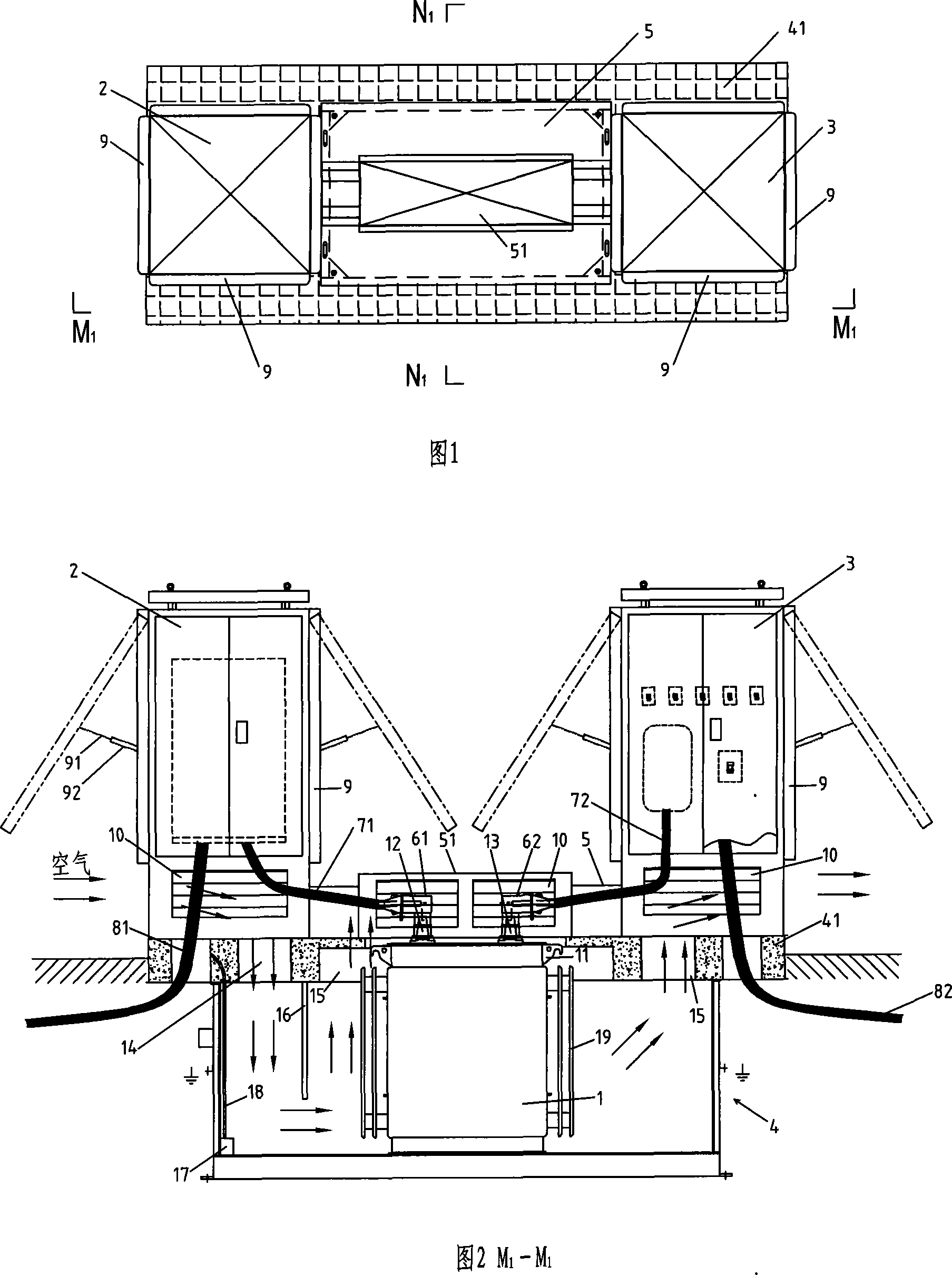
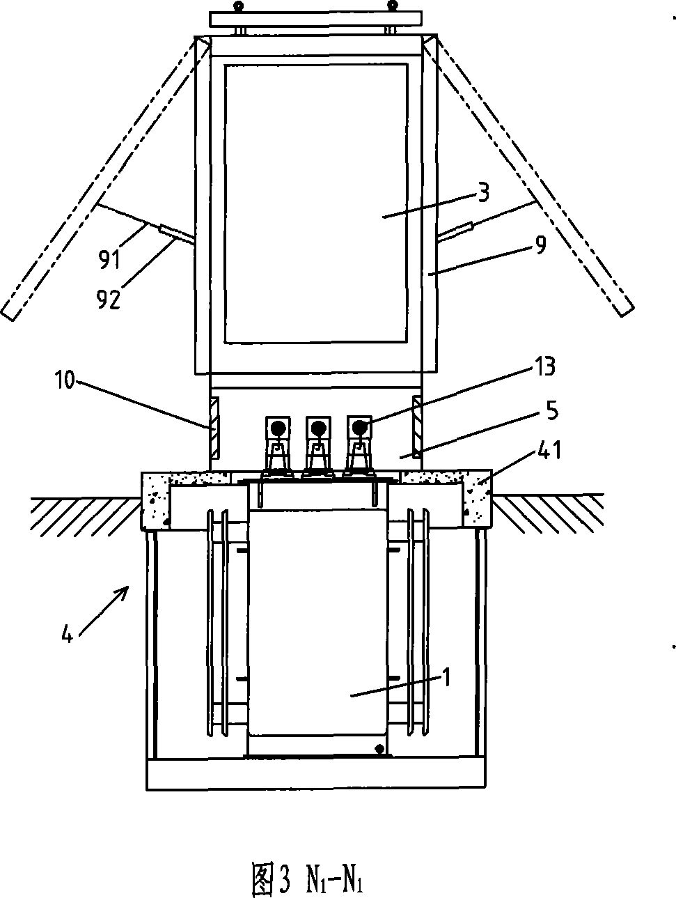
[0034] Embodiment 1 of the present invention, as shown in Figures 1 to 3, Figure 13, and Figure 14, is a pre-installed underground box-type transformer, including a transformer 1, two power distribution cabinets 2, 3, a prefabricated pit foundation 4 and The pit operation box 5, the two power distribution cabinets 2 and 3 are high-voltage power distribution cabinets and low-voltage power distribution cabinets respectively, the transformer 1 is set in the prefabricated pit foundation 4, and there are lifting lugs 11 on both sides of the top of the transformer 1 . The high and low voltage power distribution cabinets are respectively arranged on both sides above the transformer 1, the pit operation box 5 is located between the two power distribution cabinets 2 and 3, the high and low voltage power distribution cabinets and the pit operation box 5 are located on the ground plane , so that the high and low voltage terminals 12 and 13 of the transformer 1 are all higher than the gro...
Embodiment 2
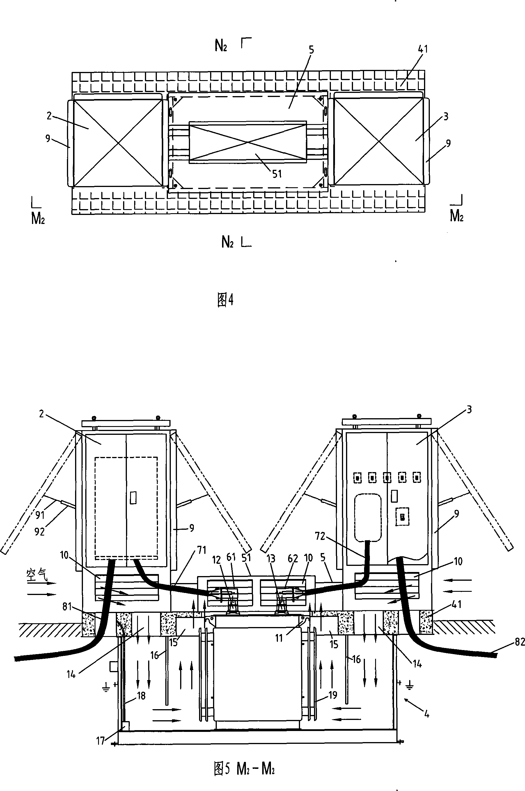
[0038] Embodiment 2 of the present invention is as shown in Figures 4 to 6. The difference from the previous embodiment is that, on each power distribution cabinet, advertising light boxes 9 are arranged on three sides except the front, and the installation of the light boxes Mode is the same as embodiment 1. And in this embodiment, two vertical deflectors 16 are installed in the prefabricated pit foundation 4, and the tops of the two deflectors 16 are fixedly installed on the pit cover 41, and the two deflectors 16 are symmetrical Arranged on both sides of the transformer 1, and respectively located between the ventilation channel 14 under the high / low voltage power distribution cabinet and the ventilation channel 15 under the pit operation box 5, the external air is ventilated by the high voltage power distribution cabinet and the low voltage power distribution cabinet into the prefabricated pit foundation 4 through the ventilation channel 14 on the pit cover plate 41 to exc...
Embodiment 3
[0040] Embodiment 3 of the present invention is shown in Figures 7 to 9. The difference from the previous embodiment is that on each power distribution cabinet, except for the inner side adjacent to the pit operation box 5, the remaining three sides Advertisement light boxes 9 are all arranged on the top. The installation method of the light box is the same as in Embodiment 2.
PUM
 Abstract
Description
Claims
Application Information