Flue gas condenser

A flue gas condenser and condenser technology, applied in water shower coolers, heat exchanger types, indirect heat exchangers, etc., can solve the problem of condensed water corrosion, limited heating area and heat transfer efficiency, and inability to condense flue gas Water vapor effect and other issues, to achieve the effect of preventing erosion, prolonging the service life and avoiding premature damage

Active Publication Date: 2008-07-16
FOSHAN SHENGKAI HEAT ENERGY EQUIP CO LTD
View PDF0 Cites 22 Cited by
  • Summary
  • Abstract
  • Description
  • Claims
  • Application Information

AI Technical Summary

Problems solved by technology

However, the dew point of water vapor in flue gas is low, generally below 60°C. To recover this part of heat, it is necessary to overcome the limitation of small heat transfer temperature difference. However, due to the limited heating area and heat transfer efficiency of finned tubes and heat pipes, only When the temperature of the flue gas drops to about 80°C, the effect of condensing the water vapor of the flue gas cannot be achieved; at the same time, when the water temperature in the heat exchanger is lower than the dew point temperature of the flue gas, there will be condensation, and the condensed water is acidic (PH=4~5 ) and dissolve more oxygen and carbon dioxide, and the heat exchanger is generally a metal product, so the condensed water has a significant corrosion effect on the equipment. If the flue gas contains sulfur, the corrosion will be more serious

Method used


Image

  • Flue gas condenser
  • Flue gas condenser
  • Flue gas condenser

Examples


Embodiment 1

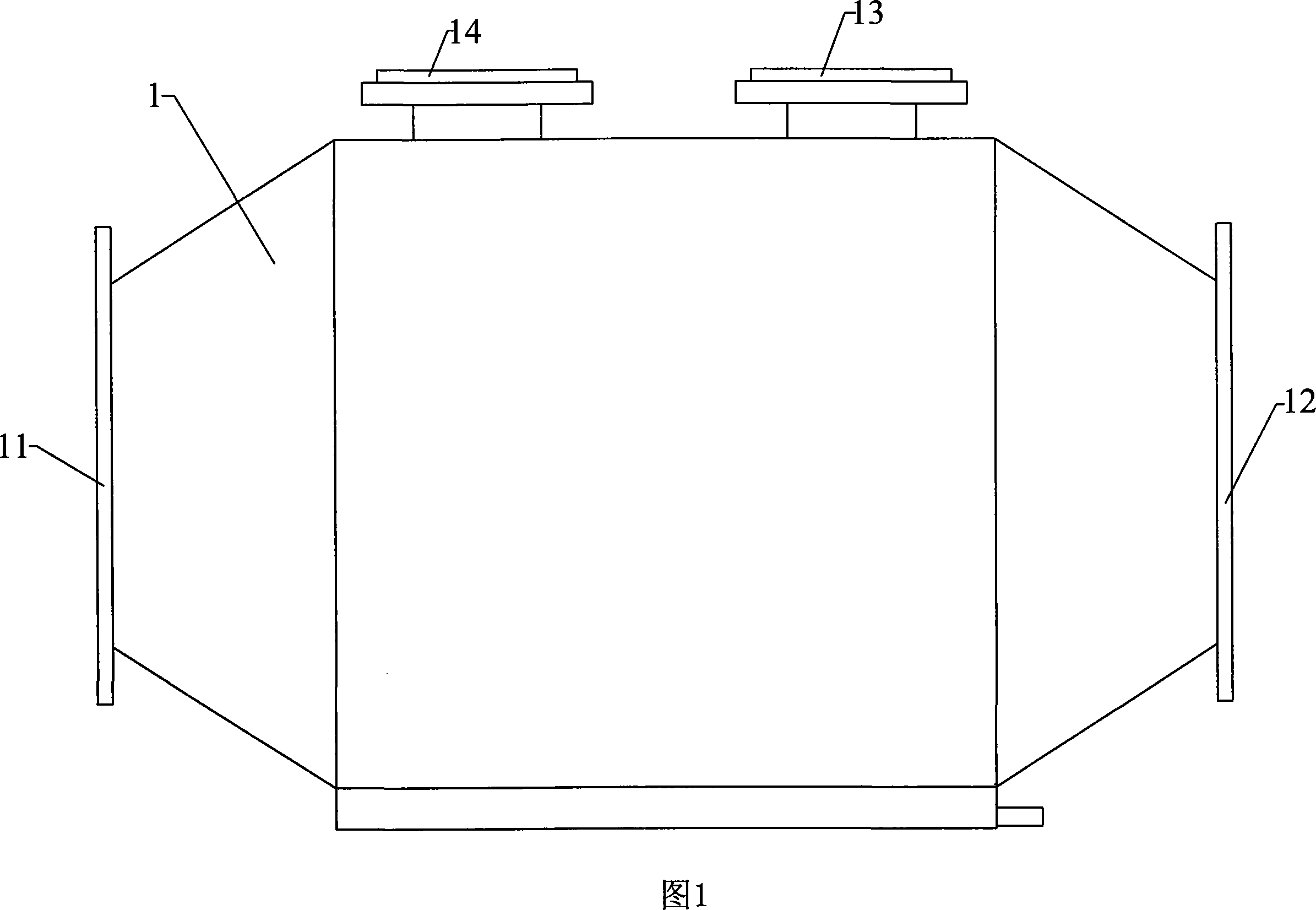
[0023] As shown in Figure 1, the present invention is a new type of flue gas condenser, which includes a shell 1 made of glass fiber reinforced plastics, or the inner cavity is lined or coated with anti-corrosion materials. The casing 1 is provided with a flue gas inlet 11 , a flue gas outlet 12 , a cooling water inlet 13 and a cooling water outlet 14 . Among them, the flue gas inlet 11 and the flue gas outlet 12 are horizontally arranged at both ends of the casing, the cooling water inlet 13 and the cooling water outlet 14 are radially arranged on the top of the casing, and the cooling water inlet 13 and the flue gas outlet 12 are located on the same side, cooling The water outlet 14 and the flue gas inlet 11 are located on the same side. Cooling water and flue gas are arranged in countercurrent.

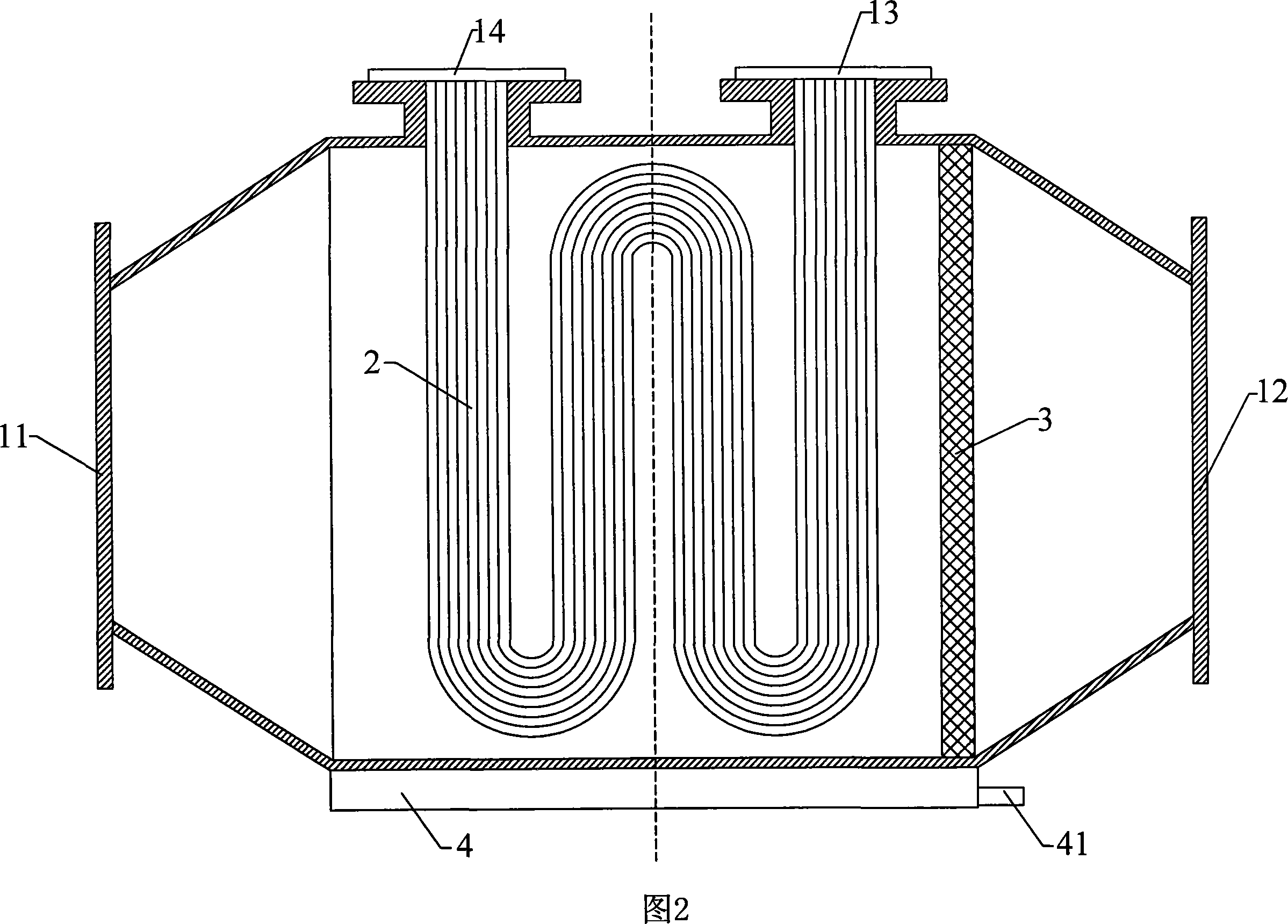
[0024] As shown in Figure 2, the middle part of the condenser is provided with a heat exchange element 2, the heat exchange element 2 is a coiled capillary made of polytetrafluoro...

Embodiment 2

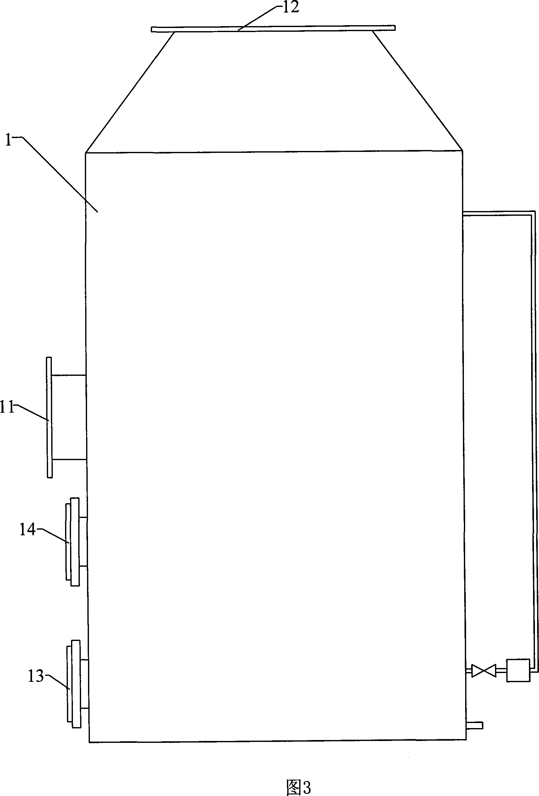
[0029] As shown in Fig. 3, this embodiment is another embodiment of the present invention. Wherein, the flue gas outlet 12 is radially arranged on the top of the casing 1, the flue gas inlet 11 is arranged on the side wall of the casing 1, the cooling water inlet 13 and the cooling water outlet 14 are arranged on the spray water tank of the spray device described below, and the cooling water inlet 13 is located below the cooling water outlet 14. Cooling water and spray water are arranged in countercurrent.

[0030] As shown in Fig. 4, this condenser is also provided with spraying device 5, and it comprises: - has the spray tank 55 of water level monitor, is located at the bottom of condenser, is built-in the coil type capillary tube that polytetrafluoroethylene is made , the two ends of the capillary are respectively connected with the cooling water inlet 13 and the cooling water outlet 14 arranged on the spray water tank, while the minimum water level in the spray water tank...


PUM


Abstract

The invention discloses a flue gas condenser, comprising an outer casing, a heat exchanging component, a flue gas inlet, a flue gas outlet, a cooling water inlet and a cooling water outlet. The heat exchanging component is a capillary, two ends of which are respectively connected with the cooling water inlet and outlet. Compared with the prior art, the invention enlarges a heated area of the heat exchanging component so as to further recycle heat and to more effectively enhance the heating efficiency of the equipment. Simultaneously, the PTFE and anti-corrosion materials are adopted to effectively prevent the corrosion of acid condensed water so as to avoid early damage due to corrosion to the condenser and to prolong the service life of the equipment.

Description

technical field [0001] The invention relates to thermal equipment, which belongs to the energy-saving technical field of fuel oil (gas) and hydrogen-containing fuel equipment, in particular to a novel flue gas condenser. Background technique [0002] The exhaust gas temperature of oil-fired and gas-fired boilers is relatively high, generally above 150°C, especially for steam boilers, many of which exceed 200°C; the exhaust gas temperature of gas water heaters is 160-180°C; the exhaust gas temperature of wall-hung boilers is 120°C about. At the same time, oil and gas contain a large amount of hydrogen, among which the hydrogen content in fuel oil accounts for about 11-14% of the fuel components, the hydrogen content in gas accounts for about 20% of the fuel components, and the natural gas is as high as 25%. The combustion of fuels with more hydrogen elements produces a large amount of water vapor, which makes the flue gas carry a large amount of latent heat of vaporization. ...

Claims


Application Information

Patent Timeline
Patent Type & Authority Applications(China)
IPC IPC(8): F28C1/02F28C1/08F28D7/08
Inventor 何嘉明成琳国
Owner FOSHAN SHENGKAI HEAT ENERGY EQUIP CO LTD
Why Eureka
Try Eureka