Voltage-current sensor

A voltage, current and sensor technology, applied in the field of sensors, can solve the problems of differences in collected voltage and current signals, prone to magnetic saturation, signal analysis errors, etc., to avoid coupling unnecessary electric fields, reduce the risk of capacitor breakdown, and avoid Effects of Magnetic Saturation Problems

Inactive Publication Date: 2008-07-16
BEIJING NAURA MICROELECTRONICS EQUIP CO LTD
View PDF0 Cites 14 Cited by
  • Summary
  • Abstract
  • Description
  • Claims
  • Application Information

AI Technical Summary

Problems solved by technology

[0007] From the above-mentioned voltage and current acquisition scheme, since the magnetic ring O occupies a certain space around the transmission line, it is difficult to connect the capacitor K to the same position as O, resulting in differences in the positions of the collected voltage and current signals. In the circuit, the voltage and current are not only a function of time but also a function of position, which will lead to errors in the subsequent signal analysis. At the same time, the magnetic ring O is prone to magnetic saturation under high current conditions, which may cause the collected current signal and The current signal on the main circuit no longer changes in a linear relationship, and serious errors occur; in addition, because the capacitor C1 that collects the voltage signal has to withstand a high voltage, it is difficult to select the device, and with the increase of power, The voltage on C1 is also higher, and breakdown accidents are prone to occur

Method used


Image

  • Voltage-current sensor
  • Voltage-current sensor
  • Voltage-current sensor

Examples


Embodiment Construction

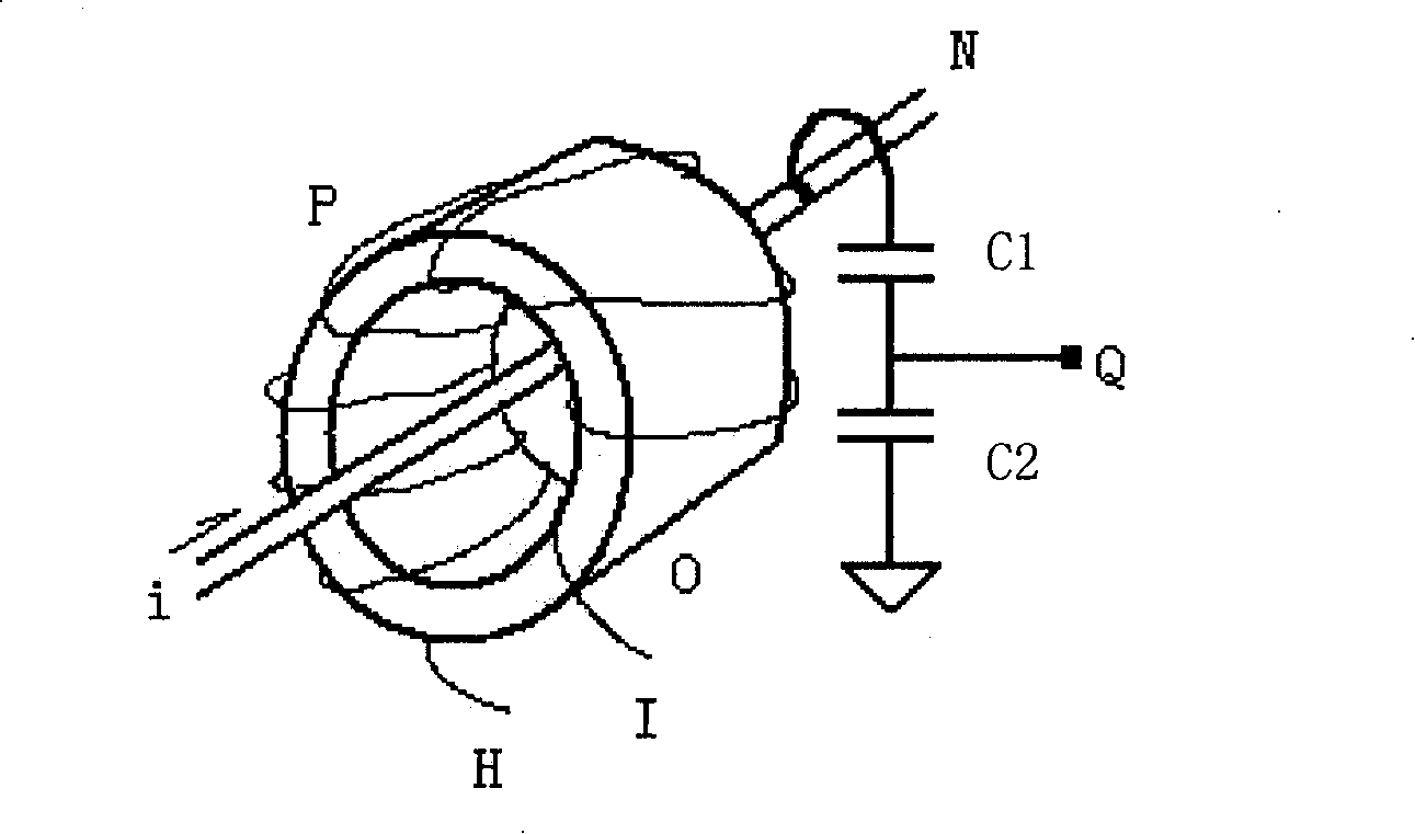
[0028] The invention provides a sensor for collecting voltage and current signals on a transmission line. Using the sensor can ensure that the signal collection points of the voltage and current are at the same position, and can reduce the risk of capacitor breakdown and avoid the problem of magnetic saturation.

[0029] For better describing the present invention, now in conjunction with accompanying drawing, the specific embodiment of the present invention is described:

[0030] The present invention provides a voltage and current sensor, including a voltage sampling device 1 and a current sampling device 2, such as Figure 4 As shown, the current sampling device 2 is located on one side of the sampling line 3; during installation, the center of the voltage sampling device 1 is aligned with the center of the current sampling device 2, so that the voltage sampling point and the current sampling point can be at the same Position; there is a shielding layer 4 between the curre...


PUM


Abstract

The invention provides a sensor which collects voltage and electric current signals in a transmission circuit, which more particularly comprises a voltage sampling device and an electric current sampling device; wherein, the electric current sampling device is arranged at one side of a sampling transmission circuit; a shielding layer is arranged between the electric current sampling device and the sampling transmission circuit; a voltage-dividing capacitor C11 arranged inside the voltage sampling device consists of conducting elements and insulating media which are sheathed on the sampling transmission circuit. The sensor can ensure that the collecting points of the voltage and electric current signals lie in the same position, avoid errors that appear in subsequent signal analyzing and unnecessary electric field that is coupled by coils in the coupling magnetic field, reduce the risks of puncturing the capacitor, and get rid of the problem of magnetic saturation.

Description

technical field [0001] The invention relates to the field of sensors, in particular to a sensor for detecting voltage and current in a transmission line. Background technique [0002] At present, in the manufacturing process of semiconductor products, plasma is often used to complete the etching process of semiconductor wafers. The plasma is generally generated by powering the plasma cavity through a radio frequency RF power supply. The commonly used radio frequency power supply The operating frequency is 13.56MHz, the output impedance is 50Ω, and it is connected with the reaction chamber through a coaxial cable with a characteristic impedance of 50Ω. During the etching process of the semiconductor wafer, the gas composition and pressure in the reaction chamber are constantly changing, therefore, the impedance of the plasma as a load is also constantly changing, and the internal resistance of the radio frequency power supply is fixed at 50Ω, so, The impedance mismatch betwe...

Claims


Application Information

Patent Timeline
Patent Type & Authority Applications(China)
IPC IPC(8): G01R15/18G01R15/06G01R19/00H01F27/36
Inventor 申浩南
Owner BEIJING NAURA MICROELECTRONICS EQUIP CO LTD
Why Eureka
Try Eureka