
Submarine mechanical claw structure

An underwater manipulator and gripper technology, which is applied to manipulators, underwater operation equipment, ships, etc., can solve the problem that the specific structure of the gripper is not given, the specific structure of the hydraulic gripper is not given, and the specific structure of the gripper of the manipulator is not given. structural form and other issues, to achieve the effect of light weight, simple structure and flexible movement

Inactive Publication Date: 2008-07-23
HARBIN ENG UNIV
View PDF0 Cites 19 Cited by
  • Summary
  • Abstract
  • Description
  • Claims
  • Application Information

AI Technical Summary

Problems solved by technology

[0005] "Research on Variable Structure Control Method and Application of Six-Function Underwater Manipulator" (Master's Thesis of Shenyang Institute of Automation, Chinese Academy of Sciences, 2002), "Research on Monitored Underwater Manipulator and Related Technologies" (Master's Thesis of Shenyang Institute of Automation, Chinese Academy of Sciences, 2001) mentioned the hydraulic jaws, but did not give the specific structure of the hydraulic jaws; "Development of 5-DOF Autonomous Underwater Manipulator" (China Mechanical Engineering, 2001, 12 Supplement: 16-18) The manipulator is controlled by the motor servo, but the specific structure of the jaws is not given; "Design of the Manipulator Control System for Underwater Robots" (Rock Drilling Machinery Pneumatic Tools, 2003 (4): 53-58) introduces a 7 The working principle and the composition and structure of the control system of the underwater robot manipulator with the motion function of the degree of freedom, but the specific structure of the manipulator claws is not given; 2006: 15~20) studied the pressure-adaptive electronic control system of the deep sea underwater operation manipulator and the computer control software with the closed-loop control of the manipulator position as the core. The paper did not give the specific structure of any part of the manipulator

Method used


Image

  • Submarine mechanical claw structure
  • Submarine mechanical claw structure

Examples


Embodiment Construction

[0018] The present invention is described in more detail below in conjunction with accompanying drawing example:

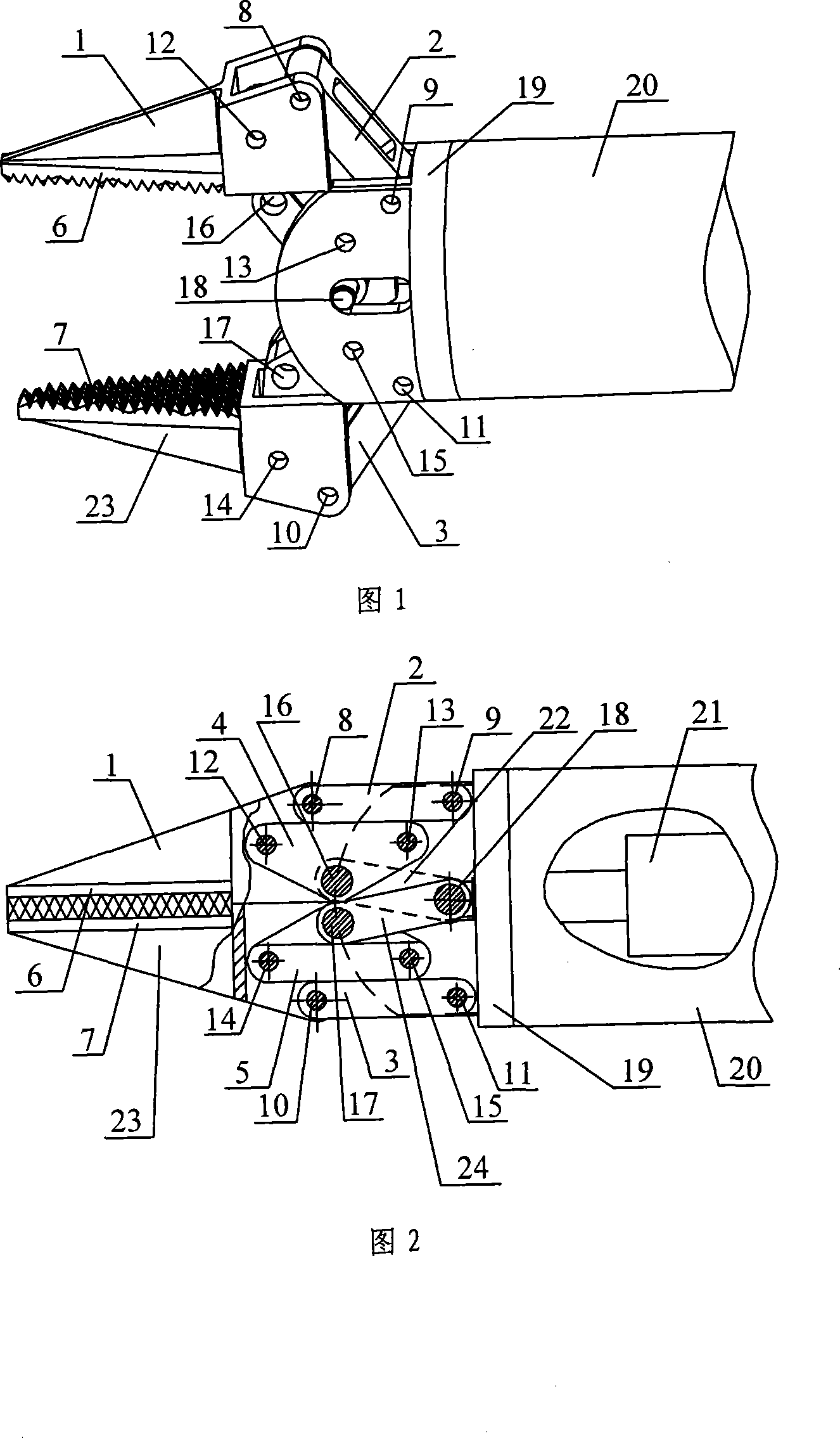
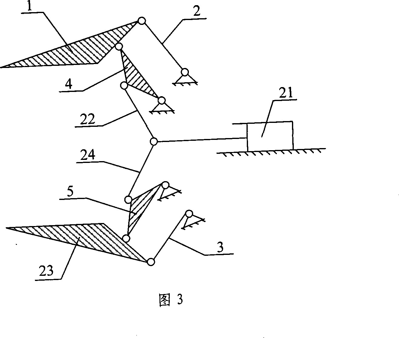
[0019] Combining Figure 1 and Figure 2, the jaw structure of the underwater manipulator consists of finger claw I1, finger claw II23, outer link I2, outer link II3, inner link I4, inner link II5, rubber layer I6, rubber layer II7, Outer link pin I8, outer link pin II9, outer link pin III10, outer link pin IV11, inner link pin I12, inner link pin II13, inner link pin III14, inner connecting rod small pin IV15, inner connecting rod large pin I16, inner connecting rod large pin II17, hydraulic cylinder pin 18, base 19, wrist 20, hydraulic cylinder 21 and connecting rod I22, connecting rod II24; wherein the rubber layer I6 is inlaid on the claw I1, and the rubber layer II7 is inlaid on the finger II23; the outer link I2 passes through the outer link pin I8, the outer link pin II9, the finger I1 and the base 19, the outer connecting rod II3 is connected with the finge...


PUM


Abstract

The invention provides an underwater manipulator clamping jaw structure, which consists of a claw I1, a claw II 23, an external connecting rod I 2, an external connecting rod II 3, an internal connecting rod I 4, an internal connecting rod II 5, a rubber layer I 6, a rubber layer II 7, an external connecting rod pin I 8, an external connecting rod pin II 9, an external connecting rod pin III 10, an external connecting rod pin IV 11, an internal connecting rod little pin II 13, an internal connecting rod little pin III 14, an internal connecting rod little pin IV 15, an internal connecting rod large pin II 17, a hydraulic cylinder pin 18, a base 19, a wrist 20, a hydraulic cylinder 21, a connecting rod I 22, and a connecting rod II 24.The invention is used for an underwater robot and has the advantages of simple structure, light weight, and agile movement. By the driving of the hydraulic pressure, the opening / closing movement of the clamping jaw is realized, and the clamping jaw is provided with the capability of clamping lager load; by the small range movement of the hydraulic cylinder piston, the opening / closing movement in large range of the clamping jaw is realized.

Description

(1) Technical field [0001] The invention relates to an underwater robot structure, in particular to an underwater manipulator terminal claw structure for an underwater robot. (2) Background technology [0002] The ocean is rich in biological resources, mineral resources and a large amount of energy such as oil, coal and natural gas. With the continuous shortage of resources on land, it is an inevitable trend for human beings to go to the sea. At the same time, the ocean determines the climate of various regions of the earth, and the ecological environment of the ocean is a barometer of the ecological environment of the earth. Therefore, it is necessary to monitor the environment of all parts of the ocean, including places that people cannot reach. [0003] At present, many countries in the world have realized the importance of using and developing the ocean, and have invested a lot of money, manpower, and material resources in research work in this area. The status of mari...

Claims


Application Information

Patent Timeline
IPC IPC(8): B25J15/00B63C11/52
Inventor 姚建均王立权王茁王成军
Owner HARBIN ENG UNIV
Learn More