Casting parts thermal insulation pit

A technology for pits and castings, applied to furnaces, vertical furnaces, lighting and heating equipment, etc., to achieve the effects of ensuring cooling speed and temperature uniformity, wide application range, and easy operation

Active Publication Date: 2011-06-01
SIPPR ENG GROUP
View PDF6 Cites 0 Cited by
  • Summary
  • Abstract
  • Description
  • Claims
  • Application Information

AI Technical Summary

Problems solved by technology

[0002]Large castings (such as 4×6×2.5m3 castings can weigh up to 100 tons, and even larger ones can weigh more than 400 tons) cool down very slowly after casting, especially After dropping to 500-700°C, the cooling rate will be slower and the work site will be occupied for a long time (if the temperature is too high when the box is opened, the casting will easily crack and directly affect the product quality). To solve this problem, in order to ensure product quality Under the premise, in order to improve the turnover rate of the work site, the high temperature is used to pack the box, and then the casting is quickly placed in the heat preservation pit, and the flame is sprayed inward through the through hole on the upper cover of the heat preservation pit to heat and cool down. The temperature is controlled by manually opening the cover plate. Although this method can greatly shorten the time for unpacking large castings, due to the direct heating of gas when heating and cooling, the flame temperature is high, and there is no hot air circulation system, the local temperature of the casting is too high. The uniformity is poor, it is difficult to meet the requirements of the cooling curve, the cover plate is manually controlled at low temperature, the operation is inconvenient, and the cooling curve and temperature uniformity cannot be guaranteed

Method used


Image

  • Casting parts thermal insulation pit
  • Casting parts thermal insulation pit
  • Casting parts thermal insulation pit

Examples


Embodiment Construction

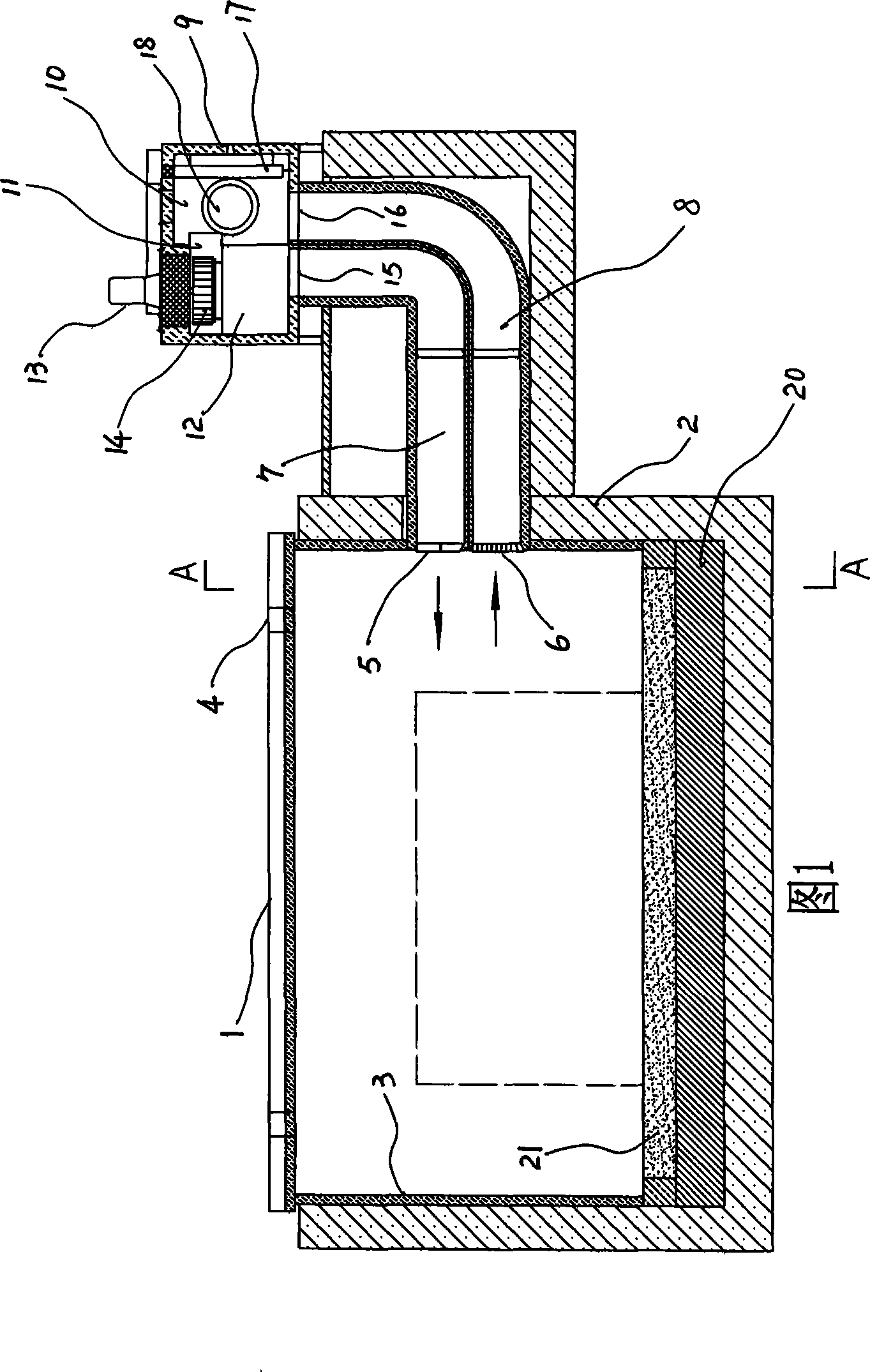
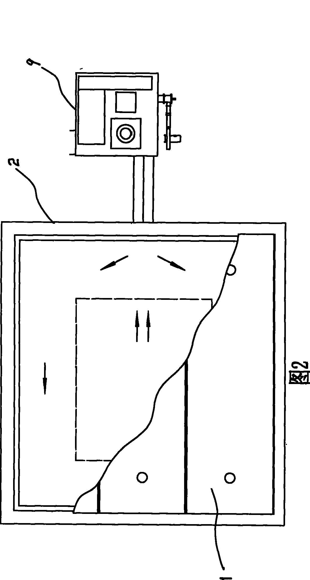
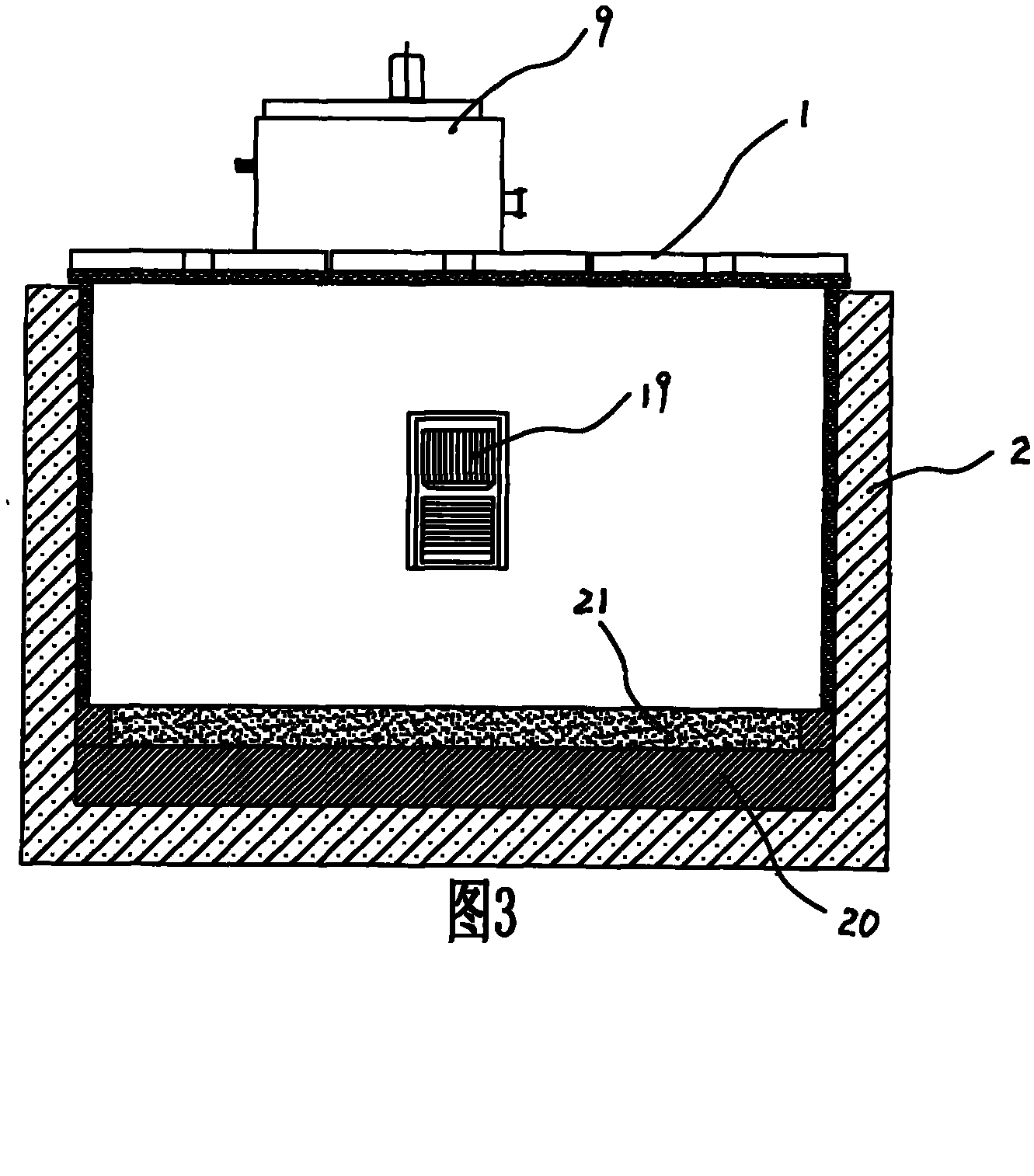
[0015] As shown in Figures 1, 2, and 3, the casting insulation pit according to the present invention includes a pit body 2 built by concrete with a split movable cover plate 1, and on the bottom wall of the pit body 2 A load-bearing heat-insulating layer constructed of heat-insulating floor tiles 20 and a sandy soil layer 21 is laid, and a refractory fiber heat-insulating layer 3 is arranged on the side wall; a plurality of vent holes 4 with covers are opened on the movable cover plate 1, On the side wall of the pit body 2, air supply and return air outlets 5, 6 are provided, and the air supply and return air outlets 5, 6 communicate with the circulating hot air device 9 through the air supply and return air pipes 7, 8. The circulating hot air device 9 is formed by communicating with a negative pressure chamber 10, a circulating air chamber 11 and a positive pressure chamber 12, and the blades 14 of the circulating fan 13 are arranged in the circulating air chamber 11; The ou...


PUM


Abstract

The invention discloses a cast thermal insulation ground pit, comprising a ground pit body with a movable cover plate built with concrete. A bearing thermal insulation layer is applied on the bottom of the ground pit, and a flame-proof thermal insulation layer is disposed on the side wall. A plurality of vents with covers are disposed on the movable cover plate, and an air vent and an air-return vent, both of which communicate with a circulating hot-air device via an air pipe and an air return pipe, are disposed on the side wall of the ground pit. Not only the empty cast thermal insulation ground pit can be heated to a required temperature quickly and evenly before the casts are hung in, but also the temperature around the cast can be kept even to the end after the casts are hung in, and cooling-curve request is satisfied completely. When the ground pit is used, the heating-up temperature is adjustable in the range of 0-650 DEG C, the heating-up velocity is adjustable in the range of 50-100 DEG C / h, the cooling velocity is adjustable in the range of 10-50 DEG C / h, and temperature uniformity in pit is +-20 DEG C. Case opening period is shortened by 30 days, so that the production period is greatly shortened.

Description

technical field [0001] The invention relates to a casting insulation pit used for large castings after being boxed at high temperature. Background technique [0002] Large-scale castings (such as 4×6×2.5m3 castings can weigh up to 100 tons, and larger ones can even weigh more than 400 tons) cool down very slowly after casting, especially after dropping to 500-700°C, the cooling speed is even slower, occupying The working site takes a long time (if the temperature is too high during boxing, the casting is prone to cracks, which directly affects the product quality), in response to this problem, on the premise of ensuring product quality, in order to improve the turnover rate of the working site, high temperature boxing is adopted , and then quickly put the casting into the heat preservation pit, spray flames inward through the through hole on the cover plate of the heat preservation pit to heat and cool down, and when the temperature is low, open the cover plate manually to ...

Claims


Application Information

Patent Timeline
Patent Type & Authority Patents(China)
IPC IPC(8): B22D30/00F27B1/10
Inventor 侯爱民王幼辉吕登五张清宽李旭斌罗通国胡加尔
Owner SIPPR ENG GROUP
Why Eureka
Try Eureka