

Aerating device for internal combustion engine
A ventilation device and internal combustion engine technology, applied in the direction of mechanical equipment, engine components, crankcase ventilation, etc., can solve problems such as the complexity of the camshaft drive mechanism and the enlargement of the periphery of the cylinder block, so as to improve ventilation performance, reduce condensation, and promote The effect of gas-liquid separation
- Summary
- Abstract
- Description
- Claims
- Application Information
AI Technical Summary
Problems solved by technology
Method used
Image

Examples
Embodiment Construction
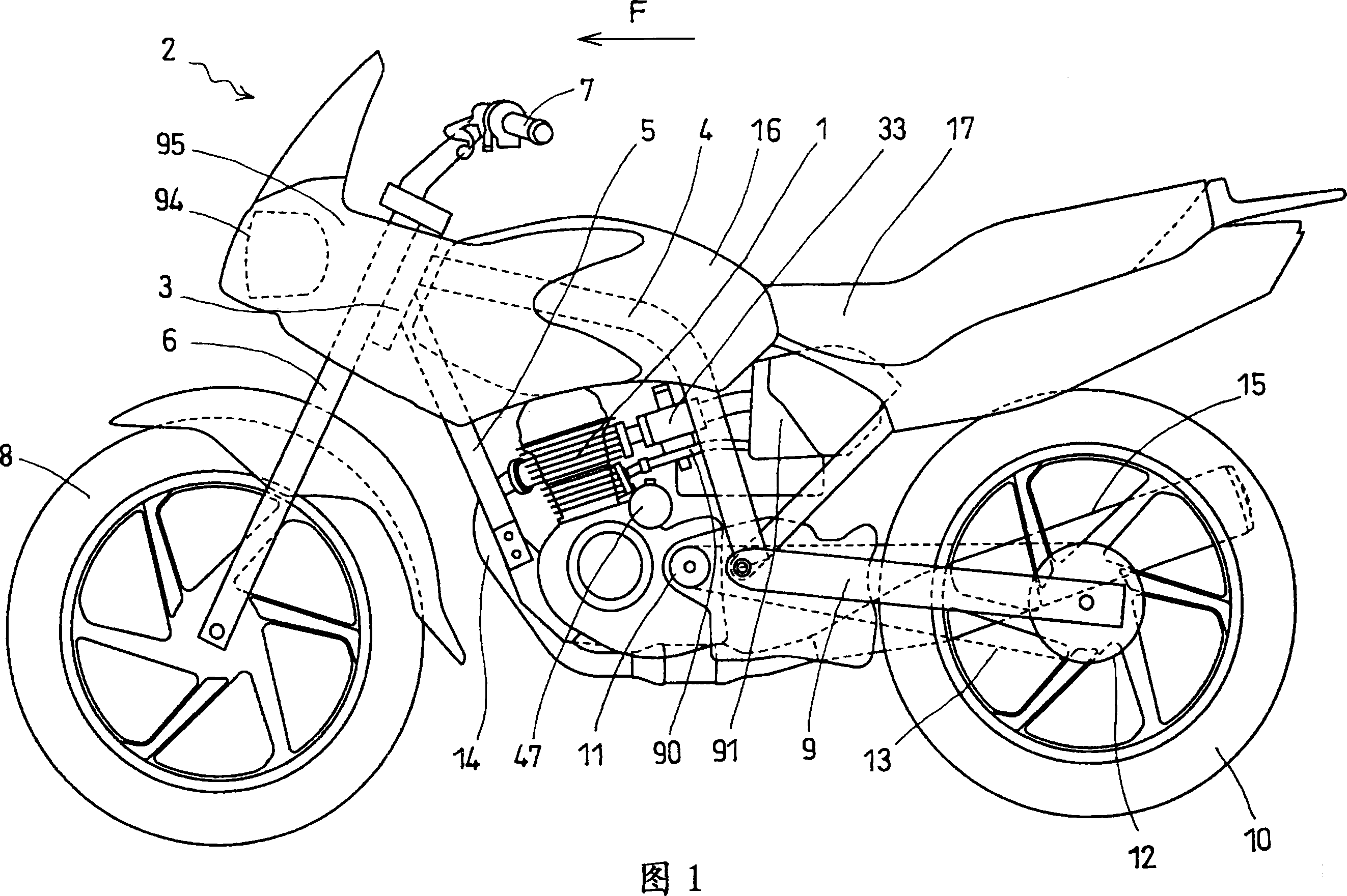
[0027] FIG. 1 is a side view of a motorcycle 2 equipped with an air-cooled internal combustion engine 1 according to an embodiment of the present invention. The direction indicated by the arrow F is the front (the same in the following figures). The main frame 4 and the lower frame 5 are connected to the head pipe 3 of the two-wheeled motorcycle 2, and extend rearward and downward respectively. The internal combustion engine 1 is suspended on these vehicle frames, and the front fork 6 is rotatably supported on the head pipe 3. A steering handle 7 is attached to the upper end of the front fork 6, and a front wheel 8 is pivotally supported on the lower end. The front end of the rear fork 9 is pivotally supported on the rear of the main frame 4, and can swing up and down. The rear wheel 10 is pivotally supported on the rear end of the rear fork 9 . The rear wheel 10 is driven by a rear wheel drive chain 13 wound around a rear wheel drive sprocket 11 mounted on the shaft end of ...
PUM
 Abstract
Description
Claims
Application Information