Hollow light guiding cone coupling vacuum transmission laser device

A vacuum transmission and transmission device technology, applied in the coupling of optical waveguides, etc., can solve the problems of easily damaged fiber input end face, high power density, and high laser power density at the fiber end face

Inactive Publication Date: 2008-08-13
INST OF ELECTRONICS ENG CHINA ACAD OF ENG PHYSICS
View PDF0 Cites 17 Cited by
  • Summary
  • Abstract
  • Description
  • Claims
  • Application Information

AI Technical Summary

Problems solved by technology

However, a small injection spot will inevitably cause a large power density, which will easily cause damage to the fiber end face
Even if the laser is injected with a 100 / 100 injection aperture, due to the small core diameter of the fiber (several μm to hundreds of μm), the laser power density at the end face of the fiber is still high, and the input end face of the fiber is easily damaged.

Method used


Image

  • Hollow light guiding cone coupling vacuum transmission laser device

Examples


Embodiment Construction

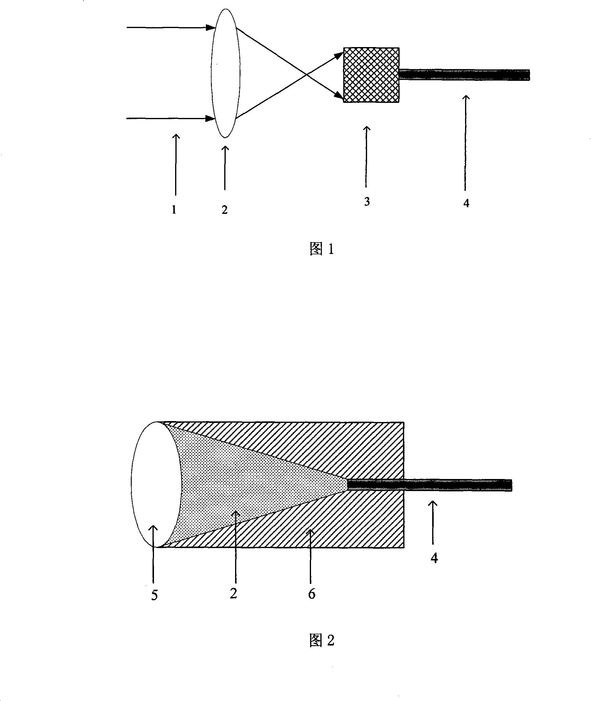
[0021] The invention realizes the coupling of high-power laser into the optical fiber by adopting the hollow light guide cone of the non-imaging element, and increases the laser damage threshold of the optical fiber end face due to the increase of the light-receiving area of ​​the injection end face. The use of hollow light guide cone and vacuum pumping technology inside the optical fiber improves the transmission efficiency of the optical fiber transmission system, reduces laser damage, and increases the laser capacity of optical fiber transmission.

[0022] Figure 1 is a schematic diagram of a hollow light guide cone coupled vacuum transmission device. In the figure, the laser light 1 is focused by the focusing lens 2, and a suitable injection spot size is obtained at the large end of the hollow light guide cone 3, and the input end of the optical fiber 4 is connected with the small end of the hollow light guide cone 3. The laser light 1 is focused by the lens 2 and injected...


PUM


Abstract

An optical fiber transmission device based on hollow light guiding cone coupling for vacuum-transmitting high-capacity laser is provided. A hollow light guiding cone is connected to the input end of the optical fiber, and small injection light spots are obtained by the hollow light guide cone to implement laser optical fiber coupling transmission. The hollow light guiding cone and the interior of the optical fiber are vacuumed or injected with inert gas to enlarge laser capacity of the optical fiber transmission system and enhance output beam quality. The invented device enlarges the lighted area on the laser input end surface effectively, reduces laser power density of the input end surface, and lowers laser damage probability. Linear and nonlinear wastage is decreased by vacuuming the laser transmission path, and the transmission efficiency of the optical fiber transmission system is increased. The invented device is provided with a simple structure, strong innovation and an evident effect.

Description

technical field [0001] The invention belongs to the field of laser optical fiber transmission, in particular to a high-power laser optical fiber vacuum transmission device based on hollow light guide cone coupling. Background technique [0002] At present, the transmission of high-power lasers through optical fibers has important applications in the fields of laser processing, laser cutting, laser ignition, laser medical treatment, and fiber lasers. However, with the demand for high-power laser applications and the development of lasers, the requirements for optical fiber transmission laser power are getting higher and higher, almost reaching the limit of optical fiber transmission laser power (GW / cm 2 order of magnitude). High-power lasers, especially narrow-pulse-width high-peak pulse lasers in high-power laser fiber transmission systems are likely to cause fiber damage. In addition, due to the high laser power density, it is not conducive to laser fiber coupling and tra...

Claims


Application Information

Patent Timeline
Patent Type & Authority Applications(China)
IPC IPC(8): G02B6/30
Inventor 赵兴海高杨蔡林飞
Owner INST OF ELECTRONICS ENG CHINA ACAD OF ENG PHYSICS
Why Eureka
Try Eureka