Tappet rod type high pressure co-rail electric-controlled oil ejector

A high-pressure common rail, electronically controlled fuel injection technology, applied in machines/engines, fuel injection devices, engine components, etc., can solve the problems of radial gap leakage, inability to establish high pressure, and impossible to achieve ultra-high pressure injection.

Inactive Publication Date: 2008-08-27
BEIJING INSTITUTE OF TECHNOLOGYGY
View PDF0 Cites 9 Cited by
  • Summary
  • Abstract
  • Description
  • Claims
  • Application Information

AI Technical Summary

Problems solved by technology

Since these parts are sliding fit, there must be a gap. The gap should not be too small, otherwise reliable reciprocating motion cannot be guaranteed, and if it is too large, the fuel leakage must be serious, and high pressure cannot be established and high-pressure injection cannot be realized.
Obviously this is an insurmountable contradiction, and with the continuous upgrading of diesel engine emission regulations, the emission regulations are becoming increasingly strict, and the diesel engine must further increase the fuel injection pressure, which makes the problem of gap sealing in these parts more prominent. In fact, due to these parts It is very difficult to further increase the injection pressure of the high-pressure common rail injector with this structure
In addition, the radial clearance between the potassium plane of the valve sleeve shoulder and the hollow plane of the injector body leaks, and the axial clearance between the minimum outer circle of the valve sleeve and the inner hole of the injector body leaks
Although these two places are static seals, as the injection pressure further increases, it is also difficult to ensure a reliable seal
Similarly, if the leakage of these parts cannot be effectively controlled, the ultra-high pressure injection in the high-pressure common rail injector is also impossible to achieve

Method used


Image

  • Tappet rod type high pressure co-rail electric-controlled oil ejector

Examples


Embodiment Construction

[0021] specific implementation plan

[0022] The present invention is described in detail below in conjunction with accompanying drawing:

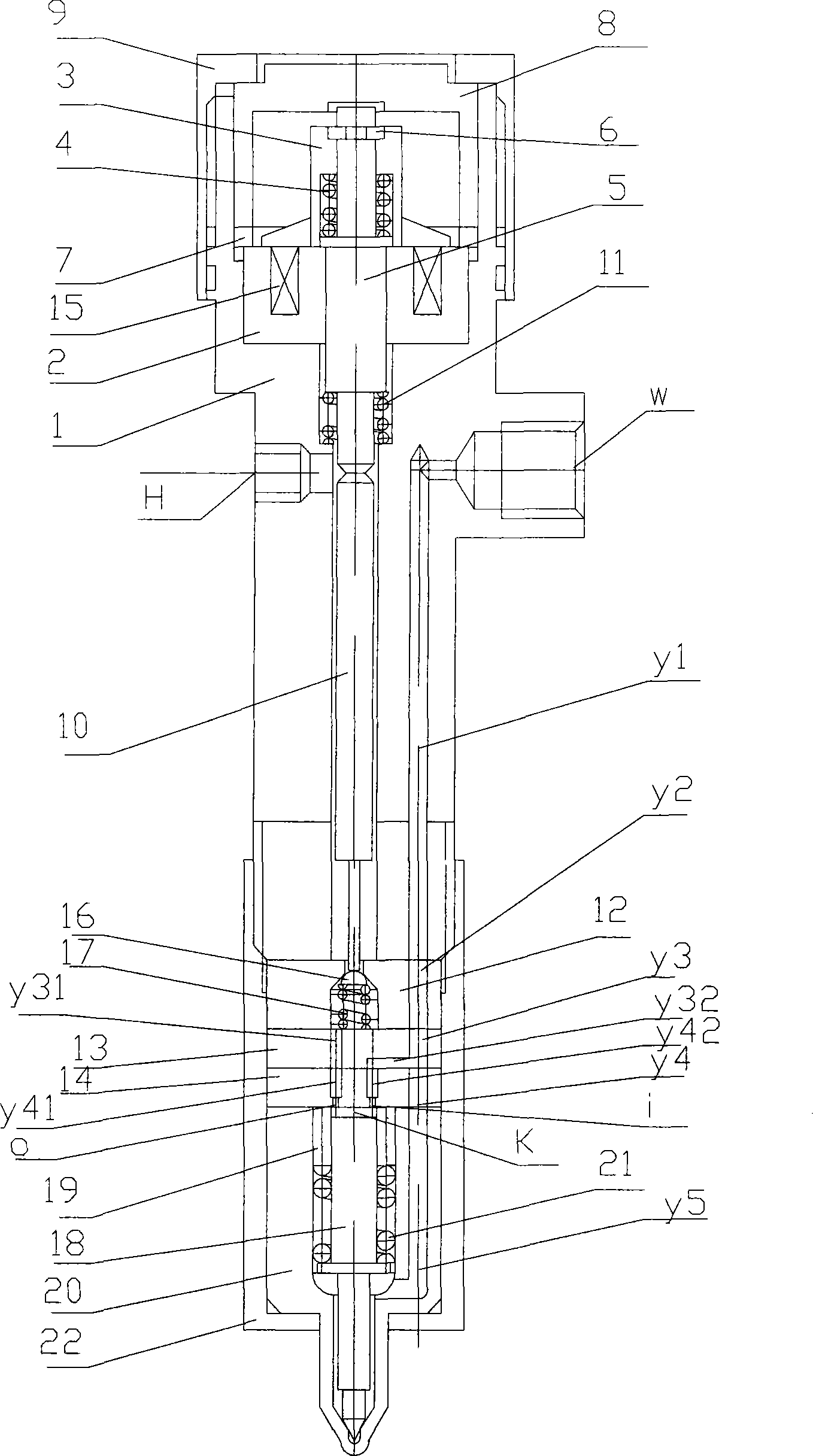
[0023] The specific structure of the present invention is as figure 1 shown. The high-speed electromagnet is a high-speed switch electromagnet, which is composed of a static iron core 2, a moving iron core 3 and a return spring 4. Exciting coil 15 is arranged in static iron core. When the moving iron core 3 of the high-speed electromagnet reciprocates under the driving of the drive circuit, the push rod 5 connected to it is driven to move up and down, and then the tappet 10 is driven to move up and down, so that the hemisphere 16 and the back-moving spring can be made to move up and down. The two-position two-way switching valve formed by 17 realizes opening and closing.

[0024] There is an oil inlet w for high-pressure fuel on the injector body, and an oil return port H for low-pressure fuel. The fuel from the high-pressure common r...


PUM


Abstract

The invention provides a tappet type high pressure common rail injector, consisting of an injector body, a high-speed electromagnet, a tappet, a pin valve component, a two-position two-way switch valve and a middle cushion block component, wherein, a central lathy pylome of the injector body is a cascade circular hole, the tappet is arranged inside a small-diameter circular hole of the injector body, the high-speed electromagnet comprises a static iron core, a movable iron core and an offsetting spring. The tappet type high pressure common rail injector has simple structure, greatly reduces the leakage of the high pressure fuel, is easy to establish the high pressure inside the injector body, and realizes the high pressure or the supervoltage fuel injection, thereby satisfying the requirements of much more stringent emission regulations of a diesel engine.

Description

technical field [0001] The invention is a tappet type high-pressure common-rail electronically controlled fuel injector, which is applied to a high-pressure common-rail electronically controlled fuel injection system of a diesel engine. Background technique [0002] The CR series high-pressure common rail electronic control fuel injection system of German Bosch company is currently the most advanced diesel engine electronic control fuel injection system, including: electronic control fuel injector, high pressure common rail, high pressure oil pump, pressure regulating valve, pressure limiting valve, Current limiter, various sensors and electronic control unit, etc. The high-pressure common rail electronically controlled fuel injector is its core and most critical components, including high-speed solenoid valve components: moving iron core, excitation coil, return spring, static iron core, oil return pipe, large nut, return spring, moving iron core Guide rod, large adjustmen...

Claims


Application Information

Patent Timeline
Patent Type & Authority Applications(China)
IPC IPC(8): F02M51/06F02M47/02F02M61/18
Inventor 王尚勇万德宙
Owner BEIJING INSTITUTE OF TECHNOLOGYGY
Why Eureka
Try Eureka