Concentric ring adverse current type hypergravity swinging bed device

A technology of high-gravity rotating bed and concentric circles, applied in chemical/physical/physical-chemical fixed reactors, dispersed particle separation, fractionation, etc., can solve the problem of large rotor liquid holdup, small rotor liquid holdup, and large pressure drop To achieve the effect of increasing the number of theoretical plates, reducing the pressure drop, and reasonable initial distribution

Active Publication Date: 2011-05-25
ZHEJIANG UNIV OF TECH
View PDF2 Cites 1 Cited by
  • Summary
  • Abstract
  • Description
  • Claims
  • Application Information

AI Technical Summary

Problems solved by technology

[0003] The purpose of the present invention is to overcome the disadvantages of large pressure drop and large rotor liquid holding capacity of the existing supergravity rotating bed, and provide a concentric circle counterflow type super gravity bed with small pressure drop, small rotor liquid holding capacity and better use effect. Rotating Bed Unit

Method used


Image

  • Concentric ring adverse current type hypergravity swinging bed device
  • Concentric ring adverse current type hypergravity swinging bed device

Examples


Embodiment 1

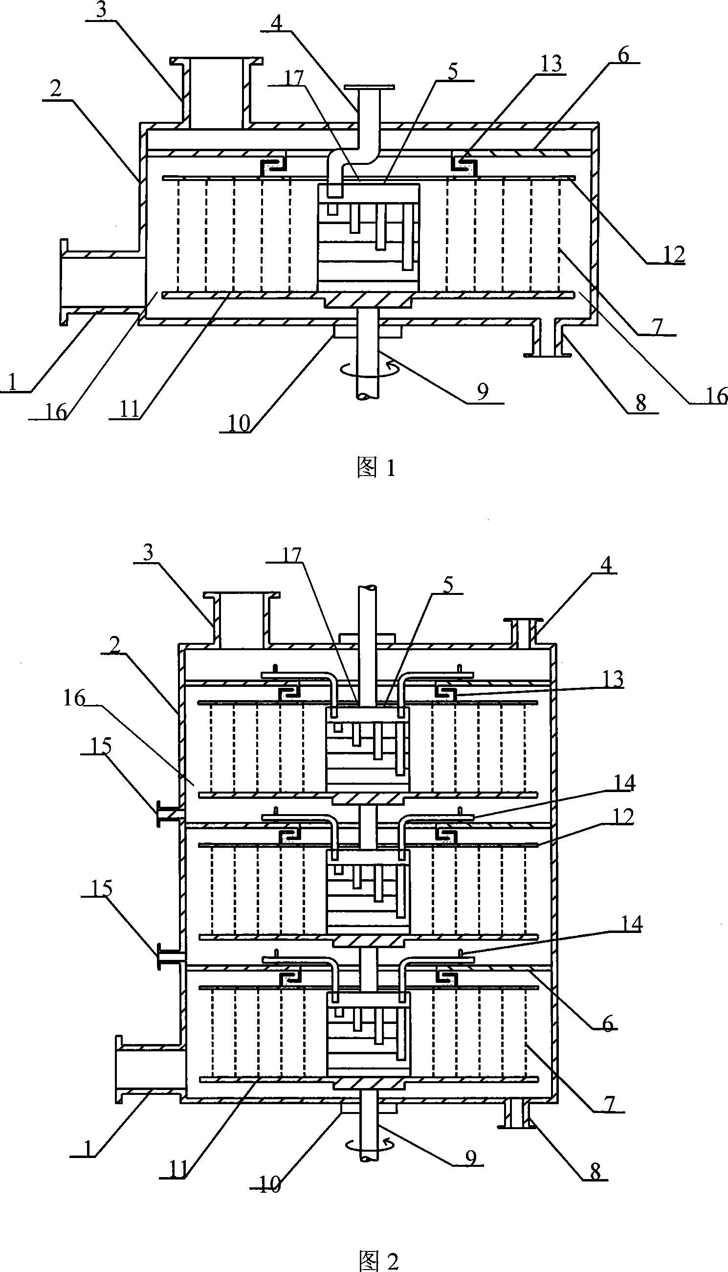
[0017] Figure 1 shows a single-layer concentric counterflow type supergravity rotary bed device, which includes a shell 2, a liquid phase inlet 4 and a gas phase outlet 3 are provided on the upper end of the shell 2, and a gas phase inlet 1 is provided at the lower end of the shell 2 and the liquid phase outlet 8, the liquid phase inlet 4 is arranged at the center of the upper end surface of the housing 2, the center of the housing 2 is provided with a rotating body 9, and a rotor is connected to the rotating body 9, and the rotor It includes a rotating disk 11 fixedly connected to the rotating body, a stationary disk 6 fixedly connected to the housing 2, a first passage opening 16 is provided on both sides of the lower end of the rotor, and a second passage opening is provided at the center of the upper end of the rotor. 17. The second channel port 17 communicates with the gas phase outlet 1 and the liquid phase inlet 4, and the first channel port 16 communicates with the gas ...

Embodiment 2

[0023] As shown in Figure 2: this embodiment is a three-layer concentric counterflow type supergravity rotating bed device, including a shell 2, the upper end of the shell 2 is provided with a liquid inlet 4 and a gas outlet 3, and the lower end of the shell 2 A gas phase inlet 1 and a liquid phase outlet 8 are provided, and the center of the housing 2 is provided with a rotating body 9 with both ends penetrating through the housing. The rotating body 9 is connected in series with a group of rotors arranged in layers from top to bottom. The rotor has three layers, and each layer of rotor includes a rotating disk 11 fixedly connected to the rotating body, and a stationary disk 6 fixedly connected to the housing 2. The upper end of the stationary disk 6 is fixedly connected with a drainage tube 14, and the rotor The two sides of the lower end of the rotor are provided with a first channel port 16, and the center of the upper end of the rotor is provided with a second channel port...


PUM


Abstract

The invention provides a concentric circularity counter-flow type super-gravity rotating packed bed, which comprises a shell, a liquid-phase inlet and a gas-phase outlet arranged on the upper end surface of the shell, a gas-phase inlet and a liquid-phase outlet arranged on the lower end of the shell, a rotating body arranged on the center of the shell, and a rotor connected with the rotating body, wherein the rotor comprises a rotating disc permanently connected with the rotating body and a static disc permanently connected with the shell, the two sides of the lower end of the rotor are provided with first access points, the center of the upper end of the rotor is provided with a second access point, the second access point communicates with the gas-phase outlet and the liquid-phase inlet, and the first access points communicate with the gas-phase inlet and the liquid-phase outlet; the rotor also comprises a concentric mesh moving coil, the concentric mesh moving coil is composed of agroup of rotating coils which are concentric with different diameters and have meshes, the bottom end thereof is permanently connected on the rotating disc, the upper end is permanently connected on a rotor cover plate, which is rotationally connected with the static disc, and the first access points and the second access point communicate with the channel of the concentric mesh moving coil.

Description

technical field [0001] The invention relates to a gas-liquid contact device, especially a concentric circle counterflow type supergravity rotating bed device, which can be widely used in absorption, rectification, heat transfer, chemical Reaction and preparation of nanomaterials, etc. Background technique [0002] Hypergravity technology is a breakthrough technology that enhances transfer and multiphase reaction processes. Utilizing the highly enhanced mass transfer process and microscopic mixing process characteristics in a high-gravity environment, we can replace the chemical tower equipment with a height of tens of meters with a high-gravity machine that is less than two meters high. Therefore, the high-gravity rotating bed is known as the "chemical Industrial Transistors". Most of the high-gravity rotating beds in the prior art have the entire rotor rotating with the shaft, and multiple rotors cannot be connected in series. The rotating bed with a single rotor cannot e...

Claims


Application Information

Patent Timeline
Patent Type & Authority Patents(China)
IPC IPC(8): B01D3/30B01D53/18B01J19/18
Inventor 计建炳徐之超俞云良隋立堂谢爱勇
Owner ZHEJIANG UNIV OF TECH
Why Eureka
Try Eureka