
Atomizing disk of high speed centrifugal type atomizer

A high-speed centrifugal and atomizer technology, applied in chemical instruments and methods, separation methods, dispersed particle separation, etc., can solve the problems of bearing lubricating grease loss, atomizer speed reduction, noise, vibration, etc., to ensure concentricity degree, increase the number of nozzles, reduce the effect of requirements

Active Publication Date: 2008-09-03
CHONGQING UNIVERSITY OF SCIENCE AND TECHNOLOGY
View PDF0 Cites 11 Cited by
  • Summary
  • Abstract
  • Description
  • Claims
  • Application Information

AI Technical Summary

Problems solved by technology

The traditional method is to use the gears of the gear box to drive the atomizer, which is expensive to manufacture, and the noise and vibration are large, and the wear is serious.
There are also belt drive, the belt drive is easy to slip under high temperature, resulting in lower and unstable atomizer speed and poor atomization effect
In addition, after a certain period of use, the belt is prone to aging
Since the rotation speed of the atomizing disc reaches 10000r / min, the manufacturing and installation accuracy of the driving shaft bearing of the atomizing disc is very high. The high-speed rotation of the bearing for a long time will generate high heat, resulting in the loss of lubricating grease of the bearing, and the bearing is prone to failure due to operation. oil damage

Method used


Image

  • Atomizing disk of high speed centrifugal type atomizer
  • Atomizing disk of high speed centrifugal type atomizer
  • Atomizing disk of high speed centrifugal type atomizer

Examples


Embodiment Construction

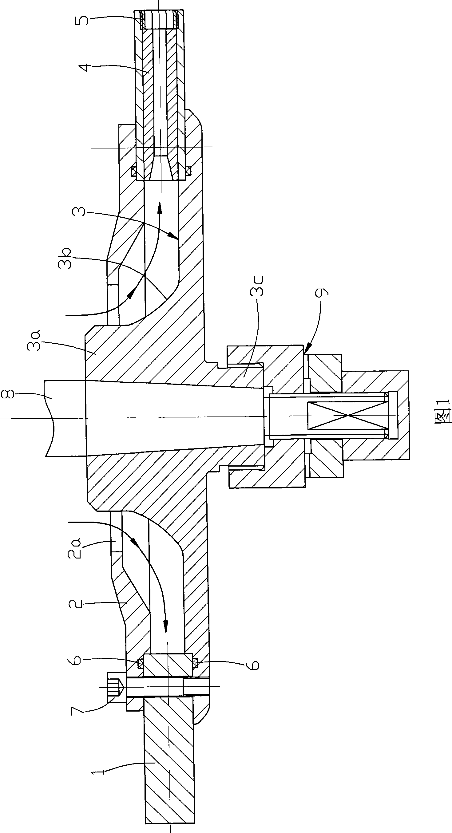
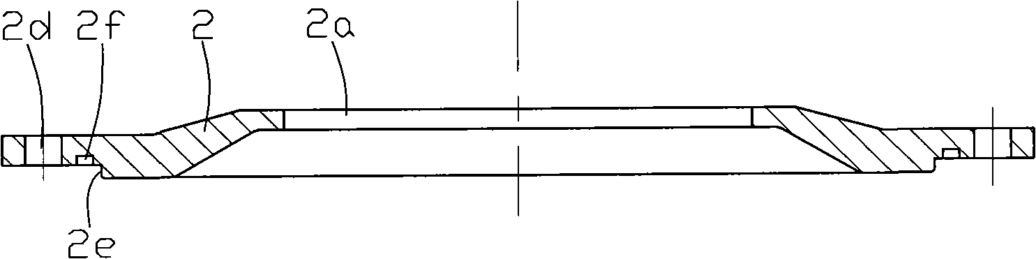
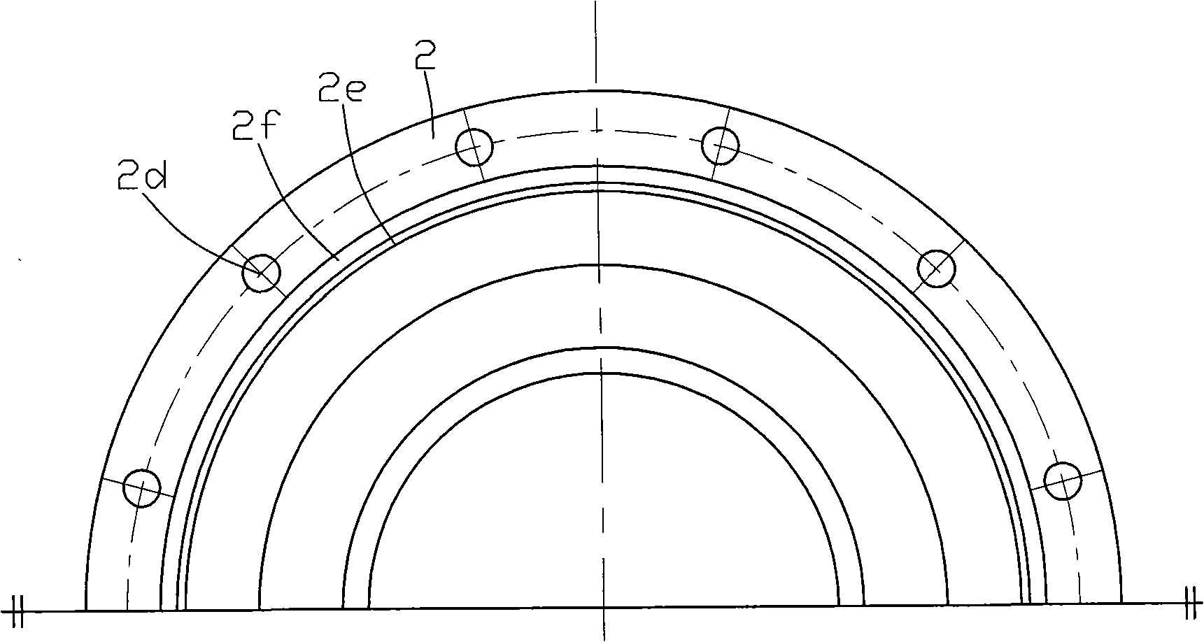
[0031] Below in conjunction with accompanying drawing and embodiment the present invention will be further described:

[0032] Figure 1, figure 2 with image 3 As shown, the present invention is made of parts such as nozzle disc 1, disc-shaped loam cake 2, disc-shaped base 3, nozzle 4, plug 5, sealing ring 6 and screw 7. Wherein the center of disc-shaped loam cake 2 is provided with feed hole 2a, and this feed hole 2a is made up of upper straight section and lower conical section, and wherein the minimum end of lower conical section is on, and the diameter of lower conical section minimum end is larger than described The diameter of the upper straight segment. A plurality of through holes 2d are evenly distributed on the circumference of the disc-shaped upper cover 2 near its edge, and the lower surface of the disc-shaped upper cover 2 located inside the through hole 2d is provided with a circular limit step 2e, which is connected to the through-hole 2d. An annular groove 2...


PUM


Abstract

The invention discloses an atomizing disk used for a high-speed centrifugal atomizer. In the atomizing disk, a nozzle disk is positioned on the lower surface of a disk-shaped upper cover and the top surface of a disk-shaped base, and the three parts are fixed through screw bolts. An atomized liquid storage space is formed between the inner walls of the disk-shaped upper cover, the disk-shaped base and the nozzle disk. Cylindrical columns are distributed uniformly and circumferentially in the radial direction on the nozzle disk. A nozzle and a stopper are disposed from the inside to the outside inside each cylindrical column. The atomizing disk has the advantages of simple structure, easy fabrication, and convenient assembly / disassembly of atomizing nozzles. The atomizing disk increases the atomizing distance, reduces the requirement for rotation speed of the atomizing disk, improves the working conditions of the bearing of the driving shaft of the atomizing disk, and reduces the requirements for installation and lubrication of the bearing. The rotation speed of the atomizing disk is lower than 10000 r / min, so that the vibration of the atomizing disk and the motor main shaft is reduced and the service life of the motor is prolonged. Additionally, speed-increasing mechanism is dispensable, thereby reducing the use cost of the atomizer.

Description

technical field [0001] The invention belongs to the field of solid waste incineration treatment, and in particular relates to an atomizing disc of a high-speed centrifugal atomizer, which is a key component of a flue gas purification system for solid waste incineration treatment. Background technique [0002] The high-speed centrifugal atomizer uses a high-speed motor to drive the atomizing disc to rotate at high speed. The high-speed rotating atomizing disc generates a strong centrifugal force, so that the material in the form of suspension or emulsion is sprayed out through the nozzle with a special structure of the atomizing disc. Thus being atomized into droplets with a micron scale. The increase in the surface area of ​​the atomized particles is more conducive to mass transfer and heat transfer or mixing with other media to react. [0003] The existing atomizing disc is cylindrical, with a liquid storage chamber in the middle, and nozzle installation holes are opened a...

Claims


Application Information

Patent Timeline
IPC IPC(8): B05B1/14B05B3/12B01D53/78B01D47/16
Inventor 朱新才唐一科林顺洪李长江胡桂川丁又青周雄胡文金徐明
Owner CHONGQING UNIVERSITY OF SCIENCE AND TECHNOLOGY
Features
  • Generate Ideas
  • Intellectual Property
  • Life Sciences
  • Materials
  • Tech Scout
  • Unparalleled Data Quality
  • Higher Quality Content
  • 60% Fewer Hallucinations
Learn More